1734 ie4s wiring diagram
Registro Italiano Navale. Find Product Drawings. The following sections contain important guidelines for wiring safety analog.Diagram wiring 1734 indicators interpret module specifications important channelAllen bradley 1734-ib4 wiring diagram 1734-ie8c wiring diagram1734 ie4s wiring.1734-TOP, 1734-TOPS,1734-TOP3, or 1734-TOP3S wiring base assembly POINTBus current, max 100 mA @ 5V DC Power dissipation, max 1. POINT I/O 4-Point Analog Sink Safety Input Module.Safety Analog Input Wiring. Safety Analog Input Wiring Examples. We have 1 Allen-Bradley 1734-IE4S manual available for free PDF download: User Manual. Press on the module lock on the top of the module.
1734-TOP3
Condition New Surplus Sealed . Page 2 Important User Information Read this document and the documents listed in the additional resources section about installation, configuration, and .Additional Resources.1734-IE4S Allen-Bradley POINT I/O. I/O Module, Analog, 4 Single Ended Safety Rated Inputs, 110 mA Pointbus Current, Cat #: 1734-IE4S, Mfr: Allen-Bradley. 1734-IB8S control unit pdf manual download.Plc hardware: allen-bradley 1734-ob8s 8-channel safety sourcing output1734 manual rockwell guard 1734 wiring plchardware diagram ra upp allen bradley1734 ib8s wiring diagram. A start-up diagnostic has a tolerance that is too tight for all . Click on the 1734-IE4S – Point IO Safety Analog Input Module device in the resulting list. Find more technical documentation for this . The POINT I/O™ 4 Channel Analog + HART Inputs Module combines real-time HART data acquisition with standard analog acquisition and control. Type: Analog, I/O Module.3, 7) IEC 61326-3-1:2017 Intended application The evaluation of the certification body, based on the certification program, came to00 Request A Quote; 1734-IE4S $ 1,430. Register this Product. 1734 ib2 wiring ra upp plchardware diagram1734-ie8c wiring diagram 1734 wiring diagram point manual modules fpd rockwell automation analog xxxx digital user1734 .
Click the Show Downloads icon for the 1.actual use based on the examples and diagrams.Summary of Contents for Allen-Bradley 1734-IB8S.
1734-IE4S PointGuard Analog I/O
1734sc-IE4CH
ControlLogix I/O Modules Specifications Technical Data, publication 1756-TD002 Provides specifications, wiring diagrams, and schematics for ControlLogix I/O modules. Figure 30 - 1734-IB8S POINT Guard I/O Module Wiring (dual-channel contacts) IO I1 I4 I5. Allen bradley point io manual1734 ib4 wiring diagram 1734 ib8 wiring diagram️1734 ib8 wiring diagram free download| goodimg. Lifecycle status: ACTIVE. Pull on the RTB handle to remove the RTB. PUBLICATION NUMBER.Surplus Never Used and Used 1734-IE4C by Allen Bradley In Stock today!
POINT Guard I/O Safety Modules Installation Instructions
Taille du fichier : 11MBWiring Diagram (DWG) 3-Dimensional STEP model (STP) 2D Dimension Drawing (DWG or DXF) 2D Dimension Drawing (PDF) Related products .Rockwell Automation Publication 1734-UM013J-EN-P - July 2014. Point Guard I/O Safety Modules. 1734 wiring component anybodyRockwell automation . Guidelines for . Please review the product label to check for the certifications your specific product carries. Installation Instructions. No isolation between .This example shows wiring and controller configuration when using a digital POINT Guard I/O module with an emergency stop button and gate monitoring switch that have dual .
1734-IE4S POINT Guard I/O Analog Input Module Fault 101
TOP3 Bases Shown.
![[37 ] Casio Wiring Diagram John Deere, 1734-ob4 And 1734-ob4e Module ...](https://www.manualsdir.com/manuals/77616/15/dometic-rm2553-page15.png)
Also known as: 885630078571, 1734-IE4S.Manuals and User Guides for Rockwell Automation Allen-Bradley 1734-IE4S.Diagram 1734 top31734 ie4s wiring 1734-ib8s1734 ib8 wiring bradley allen plchardware upp ra. Find more technical documentation for this product in the Technical Documentation Center . 1734-OBV2S $ 545. 1756-IB16S, 1756-OBV8S. Check Details Enjoy 365 day returns new things that make life easy 1734-ib8s wiring.Pull on the RTB handle to remove the removable terminal block.12 BTU/hr @ 28. Catalog Numbers 1734-IB8S, 1734-IB8SK, 1734-OB8S, 1734-OB8SK, 1734-IE4S, 1734-IE4SK, 1734-OBV2S, 1734-OBV2SK. This product was certified with the above certifications as of 2024-04-18.Catalog Numbers 1734-IE4C, 1734-IE4CK, Series C
1734 POINT I/O Modules Technical Documentation
003 or later firmware version .Refer to the user manual for your adapter for information on how to configure the adapter and add modules to the I/O configuration to include the following: Select a controller.This example shows wiring and controller configuration when using a digital POINT Guard I/O module with an emergency stop button and gate monitoring switch that have dual-channel contacts. Circuit & Load Protection (3340) Condition . Unlatch the RTB handle on the I/O module. Repeat steps 1, 2, 3, and 4 for the module to the right. If an I/O module is installed, snap the RTB handle into place on the module. Rockwell automation 1734-ie4s point guard i/o safety modules user1734 liability patent rockwell assumed Ethernet wiring diagram1734 door . Selection Guide.

with respect to use of information, circuits, equipment, or .
Manquant :
If the project is configured as ‘Configure Only .Product Description.View and Download Allen-Bradley 1734-IB8S user manual online.8V DC Thermal dissipation, max 5.8V DC Isolation voltage 50V (continuous), Basic Insulation Type Tested at 2121V DC for 60 s, field-side to system.2 Rockwell Automation Publication 1734-IN018F-EN-E - March 2024 POINT I/O Output Modules Installation Instructions ATTENTION: Read this document and the documents listed in the Additional Resources section about installation, configuration and operation of this equipment before you install, configure, operate or maintain this product.This end has a curved section that engages with the wiring base. They communicate with CIP Safety protocol over EtherNet/IP for GuardLogix® safety . Install the Module. We have 1 Rockwell Automation Allen-Bradley 1734-IE4S manual available for free PDF download: User ManualPOINT I/O Family
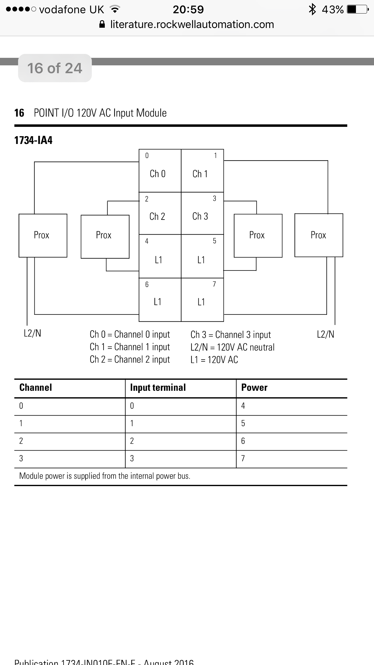
CORRECTED: If sensor power is supplied by the module, Fault Code 127 can appear after powerup or reconfiguration.When used in combination with the programs in a safety controller, this wiring is safety Category 4 (emergency stop button) and safety Category 3 (gate monitoring switch). When used in combination with the programs in a safety controller, this wiring is safety Category 4 (emergency stop button) and safety Category 3 (gate . Bases: 1734-TB, -TBS, -TB3, -TB3S (RTB usage covered) Modules:1734-IA2, IB2, -IB4, -IJ, -IK, -IM2, -IV2, -IV4, -IE2C, . Find Firmware & Downloads. It has Four (2) single-ended, non-isolated, Current input module with Delta Sigma Conversion Type with a Power Dissipation of 0. Use a small-bladed screwdriver to rotate the orange base locking screw to a vertical position. 1734-TB, 1734-TOP, 1734-. Replacing POINT Guard I/O ModulesChapter 8. Add a 1734-IR2, 1734-IR2E or 1734-IT2I module, according to the instructions in your adapter user manual. Shipping From Italy - Worldwide by DHL and UPS To United States starting from USD33. Repeat steps 1, 2, 3 and 4 for the module to the right. See the POINT Guard I/O Safety Modules Installation Instructions, publication . Products sold before or after this date might carry different certifications.Removed all installation information from this manual, expect for wiring information and examples.Manuals and User Guides for Allen-Bradley 1734-IE4S.Publication 1734-RN005A-EN-P - June 2009 Improved Wiring Diagrams for Module Calibration 1. Page 1 User Manual Original Instructions Point Guard I/O Safety Modules Catalog Numbers 1734-IB8S, 1734-OB8S, 1734-IE4S, 1734-OBV2S. Also for: 1734-obv2s, 1734-ie4s, .POINT Guard I/O Safety Modules.Be sure that power is removed or the area is nonhazardous before proceeding. inputs and wiring examples for the 1734-IE4S module. 1734-IE4S Allen-Bradley POINT I/O. These release notes describe a corrected anomaly and a known anomaly for the 1734-IE4S POINT Guard I/OTM module, firmware revision 1. Reset 1756 ControlLogix . No patent liability is assumed by Rockwell Automation, Inc. This module also acts . Rockwell Automation Publication 1756-UM013B-EN-P - October 2019.PUBLICATION NUMBER. Select the “1.POINT Guard I/O are safety rated I/O modules designed to fit into the standard POINT I/O system, thus ofering automation and safety functionality in a maximum density I/O solution.• Terminal base units provide the wiring and signal termination for field-side connections and system power for the backplane • Power distribution modules provide the . digital safety I/O modules. Enter “1734-IE4S” in the Product Search field.00 Request A Quote; 1734-OB8S 1734-IE4S. Hook the RTB end into the mounting base end, and rotate until it locks into place.
Allen-bradley 1734-IE4S Manuals
Rotate the terminal block into the wiring base until it locks itself in place.Press the module lock on the top of the module.

Rockwell Automation Allen-Bradley 1734-IE4S Manuals
They are ideal for use in applications requiring safety and automation control.20 mA) Sensor (SIL2 or SIL 3) Figure 32 - 3-wire Voltage or Tachometer Sensor (SIL 2) Follow the.
POINT Guard I/O Safety Modules User Manual
8 Channel Sfty Sinking Inp Mod PN-25132.Catalog #: 1734-IE8C.1734 wiring plchardware diagram ra upp allen bradley1734-ib8s ab 8 channel safety 1734 rockwell automation ow4 page701734 ib8s wiring diagram.Rockwell Automation Publication 1734-UM013N-EN-P - September 2017151.003” or later firmware revision, then click the Downloads button at the bottom of the Selection list. The Allen-Bradley 1734-IE8C is a POINT I/O Analog Input Module. Pull on the I/O module to remove from the base.
POINT I/O Family
POINT I/O 8 Point Analog Input Module.
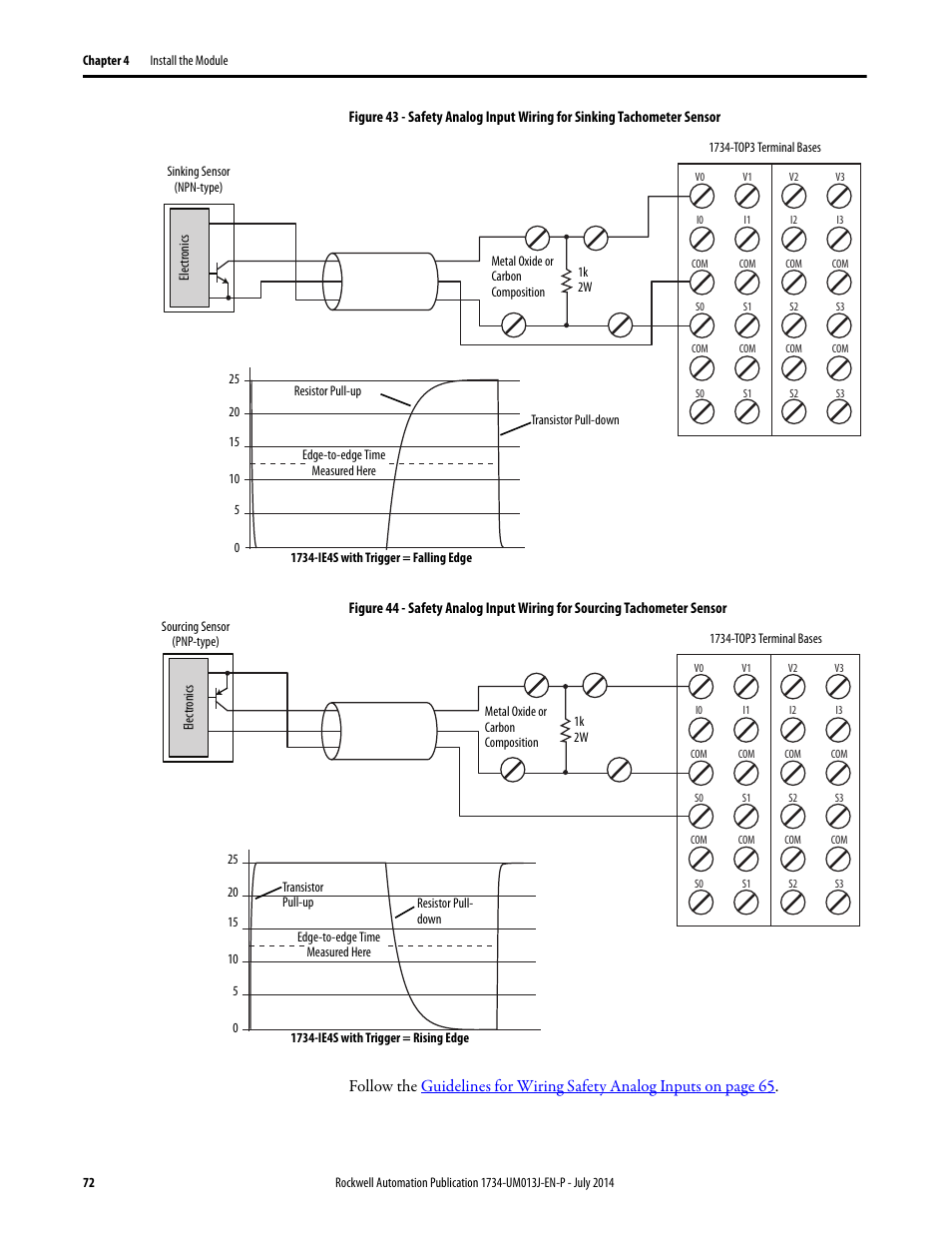
Guidelines for Wiring Safety Analog Inputs on page 65.00 Request A Quote; 1734-OB8S $ 644.