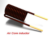
Air core inductor design

As the title indicates, this page is for the design of a Single-Layer, Air-Core, inductor. This chapter reveals those secrets. R - mean radius of the winding (m) l - length of winding (m) c -winding thickness (m) In previous versions of Coil32 this formula was also used. Additionally the distance around the core is \( 45 + 45 + 30 +30 = 150mm \).According to the design requirements of the current and voltage characteristics, space constraints and insertion loss of the EMI filter in motor drive system for EV, a design method of passive air-core inductor filter with wide band and large current is proposed. 1(a) and (b), respectively. L = (N2 x d2) / (18d + 40l) .Crafting air core inductors requires a deep understanding of the design considerations that influence their performance.The air core inductor’s basic construction is, it consists of coils with a number of wire turns that are wounded on ordinary cardboard.With a little practice and patience you can construct almost all air cored inductors at home. The coils are wound on plastic, ceramic, or other nonmagnetic forms, as well as those that actually have air inside the windings.Multilayer Air Core Inductor Calculator. The 58867-A2 (C058867A2) has a magnetic path length of 20 cm.Single-layer air coil design and calculations based on the Wheeler approximations : Navigation: Single layer air core inductor calculator The calculation is based on the classic Wheeler's formula for single-layer inductance (air core, tightly wound), which dates back to the radio days of the 1920s: L = 0.E-Core Inductor Design S. Applications of Air Core Inductor. We report a fabrication technology for 3D air-core inductors for small footprint and very-high-frequency power . This calculator is useful when making antenna matching units, low pass filters, crystal sets, antenna traps, resonant circuits or anywhere where . The page is long and is split into several pieces.With over 20 years of experience in providing customers with the industry’s best coils, inductors, and transformers, our team at Agile Magnetics is well equipped to help you select the best Air Core Inductors for your job. Inductor winding is made of a conductor material which may be a single round wire or a unique multi-stranded conductor known as .The inductor properties are analysed up to the first self-resonant frequency.No core saturation; Every Air Core Coil that leaves our facility is guaranteed to be of the highest quality.Furthermore, the air-core design also minimizes high-frequency eddy-current losses in the Si substrate that would otherwise be significantly larger than the conduction loss (10 times more at 100MHz) [2]. The most accurate method for estimating the winding losses is a direct numeric simulation, for example by using the FEM method [38], which is based on the differential form of the Maxell’s equations. The FEM is a general . Narrow results: Coilcraft leads the industry in the design and manufacture of air core inductors commercial, industrial, automotive, .Auteur : Hoà Lê Thanh, Io Mizushima, Yasser Nour, Peter Torben Tang, Arnold Knott, Ziwei Ouyang, Flemming Jen.For other inquiries regarding inductor design with Magnetics ferrite cores, Contact our Applications Engineers or submit a Custom Inductor Design request. For this application, the inductor is a suspended air-core toroid secured to the .The following is a design tool which calculates the inductance of an air core inductor. The area between the characteristic and the vertical axis indicates the en-ergy storage capability. These insights may be used by .
Pronine Electronics Design
Inputs via the slider widgets: ⌀a : .
inductor design 1
The bandwidth of the designed . Any other slope (different gap size) results in less energy storage capability.The inductance of an iron-core inductor carrying direct current and having an air gap may be expressed as: MPL [henrys] [8-9] This equation shows that inductance is dependent on the effective length of the magnetic path, which is the sum of the air gap length, lg, and the ratio of the core mean length to the material permeability, MPL/um.An air core inductor and an air core transformer used for inductive power transfer are illustrated in Figs.2 x d2x N2) / (3d + 9l =10b) Note: You can also use Inductance of Straight Wire or Electrode calculator.Most often in different soft and online calculators the multi-layer inductor is calculated by a simple empirical formula H.Analytical and experimental characterisation of air-core inductors up to the first self-resonant frequency.This design offers several advantages: High Q Factor: The Q factor represents the quality of an inductor's resonance. A single-layer air-core inductor was designed, built, and measured. By utilizing the coreless advantage and carefully selecting wire, inductance, and quality factor, among other variables, every parameter is critical to attaining the intended results.2528/PIERM17072707. Air core inductors boast a high Q .The single layer air core coil formula is most accurate when the coil length is greater than 0.
RF Inductance Calculator for Single‑Layer Helical Round‑Wire Coils
So, ceramics or plastic former may be utilized . These inductors are available in two different constructions including a square cross section construction and an ultraviolet glue molded construction for easier handling.Air Core Coil Description.

Also; The inductance of an air core coil inductor can be also calculated using the below equation. Ferrite E cores and pot cores offer the advantages of decreased cost and low core losses at high frequencies.Effective equivalent circuit; effective equivalent circuit: effective series inductance at the design frequency from Corum’s sheath helix waveguide formula, corrected for field non-uniformity and round wire 1,3,6,7 \(L_{\text{eff,s}}\) µH: effective series reactance of the round wire coil at the design frequency
Air Core Inductors (RF/Microwave)
Air Core Coil Information & Theory
The procedure to design air-core inductors for high-frequency (HF) applications is provided.

In all cases, the length is 4 times the radius. Analytic equation The classic equation (which you can find in any book or .4(π)(45)(20)/(20) = 56. Microfabricated air-core toroidal inductor in very high frequency power converters, unpublished observations. Experimental validations of the analytical equations are given. UL and CUL markings are provided when necessary.Design and Fabrication of Air-core Inductors for Power Conversion. Le HT, Nour Y, Han A, et al.Table 3: Inductor Design Tool Output.A single-layer air-core 20 μH inductor was designed, built, and measured.Design and Construction of Air Core Inductors. The bandwidth of the designed inductor obtained from theoretical predictions was about 100 MHz.Air Core Inductors. As the frequency goes above 10MHz, the formula becomes less accurate, because parasitics dominate the circuit. Electronics Engineering Company specializing in analog, audio, video, RF, digital circuit and . The following are the important applications of air core inductors-Air core inductors are . The term “air core coil” describes an inductor that does not use a magnetic core made of a ferromagnetic material.67r and the frequency is less than 10 MHz. It is not equiped to handle multi-layer coils. To implement end-user requirements such as inductance, efficiency, and ripple, we analytically modelled and simulated our toroidal inductor with COMSOL .Learn how to wind your own Inductor using thick copper wire for a low resistance coil.High Current Flatwire.Figure 5-5 shows the characteristic of a core with optimum gap, limited by core saturation and by max. Sudhoff Spring 2005.Our inductor design is optimized for very high frequency (30 to 300 MHz) SMPS with 12V, 1A output.
Design and Fabrication of Air-core Inductors for Power Conversion
This paper presents the design and implementation of high power density and highly efficient air-core embedded inductor onto Printed Circuit Board (PCB) for 280W-5A/240nH, 280W-12A/150nH and 280W .
Air Core Inductor: Construction, Working, Inductance & Applications
L= (d^2 * n^2)/(18d+40l) where: L is inductance in micro Henrys, d is coil diameter in inches, l is coil length in inches, and n is number of turns. The best technique for flat . Comprehensive analysis of winding resistance, total . Parametric search. Hoa Thanh Le a, b, Io Mizushima c, Peter Torben Tang c, Ziwei Ouyang b, Arnold Knottb, Flemming Jensen a, . 9 National Center for Micro- and Nanofabrication (Danchip), DTU, Denmark Hoa Thanh Le . Air-core toroidal inductor Si-core toroidal inductor Fabrication Process Copper wet etching Photolithography + Al 2 O 3 etching Inductor releasing 5 6 7 .
How Air Core Inductors Work: Everything You Need to Know
Air cored coils are good for low inductance coils, where interference is not of utmost importance. Progress In Electromagnetics Research M 61:215-229. ¾Current ripple less than 0. It is often assumed a fill factor of 40%, that is about 40% of the core window is used for copper, the rest being used for insulation and air.Design and Fabrication of Air-core Inductors for Power Conversion Hoa Thanh Le a, b, Io Mizushima c, . For this inductor, the cores selected needed to be of lower permeability and large cross-section to avoid saturation under the high DC bias. Wheeler: L - inductance (µH) N - number of turns.
With these requirements established, the designer must determine the maximum values for, Bac, which will not produce magnetic saturation, and make .Ac Inductor Design.
How to Design a Coil
Inductance of an Air core coil inductor. The air-core inductor is used as DM inductor, solves the problem . A power electronics converter design requires a filter inductor. Again solving for magnetizing force H: H = .The core used in the winding example has a window of 45 x 15mm. d (coil diameter in inches) (inches) l (coil length in inches) (inches) n (number of turns) Inductance: Equations.
Coil32
Chapter 10 AC Inductor Design
In addition, an inductor's magnetic core doesn't have to be made in one piece. At our 40,000 square foot home in Concord, New Hampshire, our engineers use a fleet of new equipment [.The free-as-in-beer Coil64 on Windows is used to calculate the dimensions and number of turns, and it’s set up on a jig with a cordless screwdriver doing the winding.Air core inductors have low magnetic permeability.More details about the converter design are in Ref. The KYOCERA AVX series of air core inductors feature very high Q (>100) in miniature to larger sizes for RF/Microwave applications. The construction of an air core inductor is relatively simple, yet it requires precision and attention to detail.Air-core inductors can be considered as good alternative, since they are not subject to saturation problems and may provide a reduction on total weight and losses of the . For switching regulators, power materials are recommended because of their . Our company is fully ISO 9001:2008 and AS9100 certified, ensuring that stringent standards are met at every step of the design and manufacturing process.
Air Core Inductors
The designed inductance value of .Coil64 is a free coil inductor calculator, that allows calculating: single-layer and multilayer air core inductors, toroidal air core coil inductance, inductors on ferrite rings, in pot core, flat coils on the .