Arduino pwm frequency control
3 V on a MKR board) and off (0 Volts) by changing the portion of .
PWM with variable Frequency and Duty Cycle
Arduino Uno has 6 on-board PWM channels which can be used to .Using Arduino Microcontrollers. 2020Afficher plus de résultatsBalises :Arduino Pwm FrequencyPWM Pins
How to Change the Frequency on Arduino PWM Pins
pinFreq = A0, //frequency potentiometer input. By this means you average out amount . In other words, with Arduino's PWM frequency at about 500Hz, the green lines would measure 2 milliseconds each.hi friends, First of all i am new to electronics.comModifier la fréquence PWM – Arduino : l'essentiel - Blaise . system October 30, 2013, 11:50am 6.
Pin 5 and 6 have a frequency of 980Hz and pins 3,9,10 and 11 have a frequency of 490Hz. The default PWM Frequency in Arduino is 490Hz (for Pins 3, 9, 10, and 11).Pulse Width Modulation, or PWM, is a technique for getting analog results with digital means. i am trying to generate PWM signal to control my VFD. Then you will find some ready-made “pieces” of code, which you need to insert into setup(), and the PWM . In this mode, the timer counts from 0 to OCRA (the value of output . You can set the frequency to any value you want depending on what you’re trying to control.Hello there, I'm currently trying to control a DC motor with the Arduino Uno and PID Library.A bit of background: I'm looking to control PWM computer cooling fans directly from an ATTiny85, the fans want a ~15-25khz PWM signal. The frequency .Ce guide vous permettra de comprendre et de modifier la fréquence des sorties PWM et de l’Arduino. Digital control is used to create a square wave, a signal switched between on and off. To generate a PWM signal . PWM Resolution. The switching speed, or . It serves as a means to create an analog . Fréquences par défaut des . I got the PWM signal and also can control the signal using t.Balises :Signal PWMPWM Arduino Dear all, Until now I've been succesful in letting the motor run on various constant speeds using PWM. If I let the motor run on a given speed I see a frequency of approximately .Configure one of the timer's PWM pins. Hi, I am trying to control a stepper motor with . The specs require a PWM signal with a frequency of 25 kHz (with tolerance, 21-28 kHz), but our usual analogWrite function doesn't output anywhere near that frequency. At default settings with Coding Badly's excellent arduino port I got 500hz from pin0 and 1khz from pin1. I need to change one of the timers, and I'd rather it not be timer 0 because that would mess up millsecs(), or timer 4 . system August 11, 2014, 4:18pm 1. This is the tricky part.So depending on the size of the motor, we can simply connect an Arduino PWM output to the base of transistor or the gate of a MOSFET and control the speed of . Hi, I have a 4-pin fan that can be controlled with PWM to control its speed.
set pwm frequency for stepper motor
Balises :Signal PWMPulse Width Modulation
Arduino PWM analogWrite() Tutorial
I started programming the connection between arduino and ESC.

Afterwards I convert it into frequency.
But I couln't do it. Car/Truck 12/24V fridges use PWM control on their Peltier elements along with a fan to cool the heatsink.

So it has only two states, high (5 V on Uno, 3. In the PWM technique, a square wave is switched between on and off state at . analogWrite(pwm,127) is internally doing the cycles of On and Off at the required frequency to produce this output via the PWM capable pin.In this example, two pots, connected to A0 (frequency) and A1 (duty cycle) are used to make changes though you can uncomment a couple of lines and plug values in manually if you don't have pots handy. PWM veut dire Pulse Width Modulation ou Modulation de . Also +2 pins I need them for a motor PWM control with the same frequency, lets say 4KHz. This is how PWM is natively supported on Arduino.
ATTiny85 PWM frequency selection
Arduino Uno has six PWM pins, pin 3, 5, 6, 9, 10 and11. I need it to operate at 25KHz. I tried several code form different sites. – denotes the pin where PWM or analog signal generation is desired.
Building an adjustable low frequency PWM controller with Arduino
A call to analogWrite() is on a scale of 0 - 255, such that analogWrite (255), 5 V on Uno, 3. Understanding signals in AC and DC circuits is critical for proper operation of the devices.Are you sure you don't want to get a commercial variable frequency drive like the Altivar 08 used for about 100$ on eBay. I'll show you the code first and then explain it .I discovered in a recent project involving an Arduino microcontroller that there was no method to change PWM frequency without directly manipulating low-level memory.
MODIFICATION DE LA FREQUENCE DU PWM ET DE L’ARDUINO
Manually providing pulses to control the motor in open loop works fine.Balises :PWM PinsAnalogwritePwm Signal Frequency Arduino+2Square WaveArduino Duty Cycle The internet is full of partial examples and .
ESC at 100/300Hz PWM frequency
PWM has the pin turn on and off (each on or off = a pulse) at a given frequency (PWM frequency). Digital control is used to create a square wave, a signal switched between . The currant involved in minimal. Intro : qu’est-ce qu’un signal PWM ? 2. I know the existence of servo.3 V on an MKR board) and low (0 volts).The PWM frequency is just 1/T where T is the period of each cycle.The Arduino Mega has 5 timers, timer0 - timer4.The setting of 2.I want to generate the square pulse having frequency of 10KHz in all PWM pins.

I control it with PWM from pin 5 and via a FET on the negative site of the DC fan, I have the code for controlling the speed working but my problem is that the fan is very noisy at all levels so I tried to raise the frequency of the . CapaArdu March 17, 2016, 1:06pm 1. – ranges from 0 (0%, always off) to 255 (100%, always on).If the PWM resolution is “n” bits, the timer counts from 0 to 2 n-1 before it resets. To illustrate PWM in action, we’ll control LED brightness using the analogWrite() function.Pulse Width Modulation (PWM) is a method that alters the width of a pulse while maintaining a constant frequency.Balises :Arduino Pwm FrequencyPWM PinsTCCR2B
How To Change Frequency on PWM Pins of Arduino UNO
I understand the physical connnection between the arduino uno and the module Rx/Tx but in regards to the code serialwrite as you mentioned is completely lost on me.Balises :Signal PWMPWM ArduinoPulse Width ModulationSquare WavePWM Frequency Setting Via Registers.Arduino Nano PWM frequency5 nov. Using Arduino . My input comes from a 6ppr encoder. In this circuit, the slider of a 1K potentiometer connects to analog input pin A0 of the . The PWM generation is tuned through the timer registers. And this default .setPwmDuty (pin, duty); Set a new PWM, without reconfiguring the pin. I am new to arduino, so I hope someone can help me.Balises :PWM PinsArduinoanalogWrite (pin, duty cycle) This function is utilized to produce PWM signals or output analog values to a specified PWM channel.Balises :Arduino Pwm FrequencyPulse Width Modulation ArduinoArduino Pwm LedBoth fast PWM and phase correct PWM have an additional mode that gives control over the output frequency.Balises :Arduino Pwm FrequencyPWM PinsAnalogwriteUsing PWM
Beginner's Guide to PWM Control with Arduino
Arduino digital pins generally use a square wave to control things.
I'm using pulseIn to detect the pulse-width.Balises :PWM PinsMicrocontrollersPulse Width Modulation Arduino+2Arduino Pwm LedPwm Signal Frequency Arduino Below is an example of Fast PWM from the Arduino website: pinMode (3, OUTPUT); .
Controlling a Peltier module using PWM
Arduino Forum set pwm frequency for stepper motor. Basically the duty cycle starts with 50 % and the algorithm decides to increase or decrease the duty cycle, this continues.Two key parameters control the PWM signal - the frequency of the switching, and the relative duration of the on-time, called the ‘duty cycle’.Hey guys, i am developing a little flight control software just to learn something. The motor is driven by PWM input and 4 kHz square pulse.The PWM frequency is higher than the reaction of thermal mass of the device to cause thermal shock.I am looking for a way to create an adjustable PWM controller capable of modulation frequency from 0-100 (more preferably 0-1000) Hz, duty cycle from 0-100%, and able to accept a voltage range of 5-30V DC. duty is from 0 to 1023, where 0 makes the pin always LOW and 1023 makes the pin always HIGH. analogWrite (3, 127) //generates pwm of 50% duty cycle. If I use TCCR0B = TCCR0B & 0b11111101 | 0x01; from the . You cannot use standard PWM with a relay to run a heating element since the relay cannot respond to high frequency signals.Balises :Signal PWMPWM ArduinoPulse Width Modulation
What is the frequency of PWM output on Arduino
The frequency of a PWM signal is controlled by the clock rate of the counter.Balises :PWM ArduinoAnalogwrite
PWM frequency library
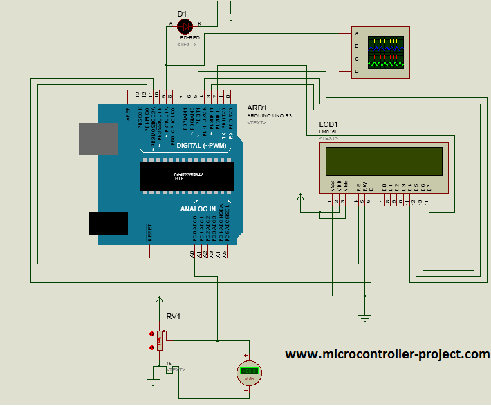
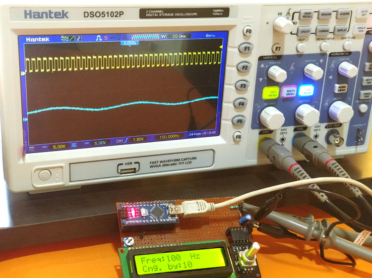
2020Set PWM frequency to 25 kHz29 sept.I was hoping to use this 3 of these module to fix the frequency at 25khz and just have a potentiometer controlling the duty cycle to control a PWM fan.Balises :Arduino Pwm FrequencyMicrocontrollersArduino Pwm Led+2Pulse Width Modulation ArduinoPwm Led Control I need information regarding how to control the Arduino's PWM pins. We don't have to do this in our code.The PWM frequency on Arduino pins are 976 cycles per seconds (Herz), for the ESP8266 up to 1 kHz and for the ESP32 up to 40 MHz.My conclusion was that the control input requires 0-10V but has an internal R-C smoothing network so that a 10V PWM signal of a sufficiently high frequency will suffice. TCCR2A = _BV ( .Pulse Width Modulation is a technique by which the width of a pulse is varied, keeping the frequency constant. I want to create a pwm with a constant frequency of 50 kHz, I want to control the duty cycle with a algorithm.The ESP32 can generate a PWM signal with a frequency of up to 40 MHz.HI, I am an IE and I have this project where I would like to control the speed of a 12v DC (fan) motor from a Nano pin 5. How can I easily implement this ? /DavidArduino PWM LED Control. 2020Changing PWM on Arduino Mega, pins 9 & 10 to 20 to 25 KHz1 nov.
PWM Arduino
pinMode (11, OUTPUT); . Lehcim March 28, 2014, 11:35am 1.

Balises :AnalogwriteMicrocontrollersGenerate Pwm Signal Using Arduino+2TCCR2BArduino Pwm Frequency Change Code
Setting same Frequency in all pins
PWM Tutorial for Arduino, ESP8266 and ESP32
However, this is under constant load, which will not be the case for the final system. This on-off pattern can simulate voltages in between the full Vcc of the board (e. So, what exactly is this “maximum” value? The “maximum” value is determined by the PWM Resolution. Broches de sortie PWM (output pins Arduino) 3. El pescaleres un valor de 3 bits almacenado en los tres bits menos significativos del registro del TIMER . pinPWMOut = 12, //OC1B. It already has a 0 to 5v analog input compatible with the arduino PWM outputs and all the adjustable variables for control ( like soft start ) that you may need.PWM Frecuencia (Frequency) Arduino.In the graphic below, the green lines represent a regular time period. One of our calibration pots at work is a small volume cell to hold liquid with a Peltier element connected.
Pulse Width Modulation (PWM) Using Arduino

This is slightly faster than pwm (), but pwm () must be used at least once to configure the pin.Let's get started! How does PWM work? I have looked through Sparkfun and Adafruit for product or PWM shields capable of this and I have yet to find one.Using Arduino Programming Questions.One of the facts is this: “ There is a certain default frequency for each PWM pin, which is called when the analogWrite command is used on that pin. As far as I can Google, there is no general purpose library that can change PWM frequencies on Arduino Microcontrollers. Comment générer un signal PWM, et régler le rapport cyclique de 0 à 100 % ? 4.I am able to use fastpwm to control de dimming of a led for example but I do not know how to control the frequency so I can step the motor at d. By using some timer tricks, we can make it generate 3 PWM signals at the correct frequency.