Basic ignition wiring diagram
I am building a 41 Chev sedan and just want to get it running enough to drive around the area and do some preliminary wiring before doing a bang up job with a prefab. 1 Working on the ignition switch and Diagnosing the problem:.1 In my experience, diagnosing a faulty ignition switch involves looking for symptoms like the lawnmower not starting, then suddenly stopping, or the key not turning in the switch. The main components of an ignition system include the battery, the ignition switch, the ignition coil, the distributor, the spark plugs, and the engine control module (ECM). Reading 1993 Subaru Ks4 Sambar Wiring Diagram. Wiring for 1942 Mercury. Spark plugs and.Regarder la vidéo6:01This is the most minimal wiring you will need to start an old motor with an HEI distributor.
How a Car Ignition System Works
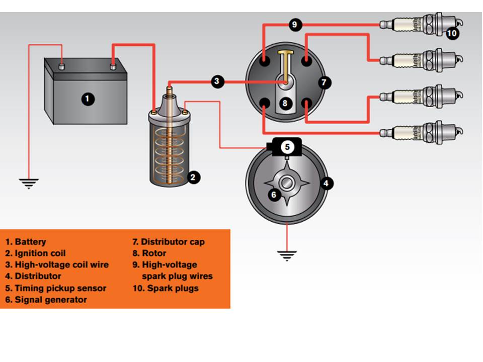
#1 · Sep 24, 2005. Using a wiring diagram specific to your vehicle, locate the wire that connects the distributor and coil. The ignition system in a typical internal combustion engine includes various components that work together to ignite the fuel-air mixture and provide power to the engine.
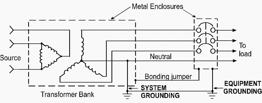
Connect the black wire to the 2 terminal. Gas furnace wiring diagrams are essential for understanding how the various components of a gas furnace are connected and how they function together.Basic Wiring Diagram: How Ignition Coil Condensers are Connected in a Typical Ignition System. Instead, these switches act as inputs to control modules—usually the body control module (BCM .

Using a multimeter to test the . All I am needing is a basic wiring diagram for an automobile. One essential component of this system is the ignition coil condenser, also . Here are the steps on how to wire a 5 pole ignition switch: Identify the 5 wires that connect to the ignition switch.Regarder la vidéo4:111.I will explain in simple layman’s terms the workings of an ignition system diagram (step-by-step).A wiring diagram is a useful tool for understanding the wiring connections and troubleshooting any electrical issues.5 (IGN) Once the wires are connected, you should be able to start the vehicle by turning the key in the ignition switch.
Flathead Electrical Wiring Diagrams
It provides the necessary information for wiring the coil correctly, ensuring that the electrical current flows smoothly and without interruption. This is followed by the alternator, which is responsible for charging the battery. This ignition takes place thanks to a group of components working together, otherwise .
How to Wire An Ignition Coil Diagram (Types & Wiring Guides)
Knowing how to properly read these diagrams can save time, .
The Definitive Guide to Yamaha Outboard Ignition Switch Wiring
The ignition coil wiring schematic depicts the electrical connections between the ignition coil and other components of the ignition system, such as the distributor, ignition switch, .
This diagram typically includes components such as an ignition coil, spark plug wires, a distributor, a crankshaft position sensor, and the ICM itself.An ignition coil wiring diagram is a schematic representation of the electrical connections between the various components of an ignition system.An ignition wiring diagram is a visual representation of the electrical connections and components involved in the ignition system of a vehicle. Following the wiring diagram provided with your ignition switch, connect the appropriate wires to their respective terminals on the back of the switch.
Wiring Diagram For Diesel Engine Ignition Switch
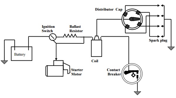
The Solenoid is further connected to the starter . Whether you need to replace a faulty ignition switch or troubleshoot an electrical problem, the diagram serves as a valuable tool in ensuring a successful repair. It simplifies the often complex wiring process, allowing .The wiring diagram of a points ignition system typically consists of a battery, ignition switch, ignition coil, distributor, points, condenser, and spark plugs.TigerT110 said: The '71 model year started with the KE prefix so assuming this applies to your Daytona the wiring diagram you want is Wiring Diagram 12 volt coil ignition KE00001 onwards. Understand the key components and connections for proper installation.
How Ignition System Works
The wiring diagram serves as a visual representation of the electrical connections and circuits that power the engine’s ignition, lights, and other electrical systems. They help explain how the necessary electrical connections are made between the ignition switch and the ignition coil, both of which are integral parts of an engine's electrical system.
Ignition Sytem: Types, Parts, Working, Diagram [PDF]
Additionally, the diagram will also display any safety features that may be included on the switch, such as .Interpreting Gas Furnace Wiring Diagrams.

This includes the wires that run from the switch to the starter motor and fuel pump, as well as the wiring for the ignition coil and ignition module. The ignition system is responsible for starting and .This video goes over the basics of wiring on pre-computer engines. The battery provides the electrical power needed to start the . Here are the steps you need to take to wire the ignition switch yourself. However, depending on the vehicle in question, you might need a push-button .
Simple Motorcycle Wiring Diagrams (Ignition & Lights)
Lamp Assemblies.Learn how to wire a basic ignition coil with this helpful diagram. Connect the red wire to the 1 terminal.coRecommandé pour vous en fonction de ce qui est populaire • Avis
How the Ignition System Works
An example of a modern computer-controlled starter solenoid wiring diagram. This diagram provides the basis for all systems, from simple one-wire setups to complex multi-wire ignition systems, so understanding it can .A 6 prong ignition switch wiring diagram provides a visual representation of how the ignition switch is wired, with six prongs representing different electrical connections. First, connect the positive terminal of the ignition coil to a 12V battery and the negative . Some system uses transistors to reduce the load on the distributor contact points. These diagrams provide a visual representation of the electrical circuitry within the furnace, including the main power supply, control board, ignition . Understanding the Ignition System in a Chevy Vehicle . Wiring for 1946 to 48 Mercury.By referring to the Chevy ignition switch wiring diagram, you can diagnose and fix issues with your vehicle’s ignition system. Make sure each wire is securely attached to the correct terminal, double-checking the labels to avoid any confusion.Next, the wiring diagram will show the connection points for the various components.

basic ignition wiring diagram
The battery provides .
How to Wire an Inboard Boat Ignition Switch: A Detailed Diagram
This diagram provides a detailed schematic of the ignition system wiring, allowing users to easily identify and troubleshoot any issues with their bike’s ignition system. Samples of engines like this include the Kohler K141, K161, K181, and some K241 engines.Sample Basic Wiring Diagram for Small Engines using Magneto Ignition with Points.
Step-by-Step Guide: Wiring a Universal Ignition Switch
141K views 1 year ago. Ignition module ford .Auteur : Automotive System
The Ultimate Guide to Understanding Ignition Switch Wire Diagrams
1971 T100R Daytona wiring
Ignition switch: https://amzn. The 12 volt coil wiring diagram is a crucial aspect for the ignition system in a vehicle. Step 5: Connect the Coil Wire to the Distributor. Wiring for 1941 Mercury. Unfortunately, in the Triumph workshop manual, there are two wiring diagrams with that title, in what was originally a manual supplement - SECTION . When it comes to the wiring diagram for a Yamaha outboard ignition switch, there are a few key components to understand.6 Symptoms Of A Bad Ignition Switch and Replacement .Start position: When the key is turned in the start position, mostly spring-loaded, Solenoid, and battery connections are established. Ignition System: The ignition system is responsible for creating a spark that ignites the air-fuel mixture inside the engine’s combustion chamber. Also, we will cover the ignition components and operation and .
Ignition Coil Wiring Diagram: A Comprehensive Guide
Before carrying out this procedure, it is relevant that you check the manual guide for the car or get an ignition switch panel wiring diagram.

to/3KoHUUm Solenoid: https://amzn.Wiring diagram for 1953-55 Truck. It illustrates the . Later motorcycles dispensed with the contact breaker in lieu of electronics, which we will cover in a later article. Unlock the ignition Module Cover.

The Gy6 wiring diagram provides a visual representation of the electrical connections and components of the engine. It is usually marked with a “+” symbol. It provides a detailed illustration of how the ignition system is wired, allowing mechanics and enthusiasts to troubleshoot and repair any issues that may arise. The purpose of the ignition system is to ignite the combustion mixture in .Home / Basics / How the ignition system works. Wiring Schematics - Mercury. (showing the electrical path and connections) Wiring for 1939 Mercury. Auto Repair Library.Figure 5 27 Breaker Point Ignition Wiring Diagram. Then, there is the distributor, which is responsible for distributing spark to the spark plugs. Wiring for 1940 Mercury. It typically has multiple positions, including Off, . The ignition switch is responsible for controlling the power supply to the boat’s electrical system and starting the engine.The ignition switch wire diagram typically includes labels for each wire, indicating its function.The wiring diagram for a universal ignition switch provides a visual representation of how each terminal should be connected to ensure the switch functions as intended.
A Visual Guide to Understanding the Basic Ignition Diagram
engine ignition coil. wiring harness. The Video Course teaches you everything about modern cars.Ignition wiring diagrams are essential components of any automotive repair job.The following are the main parts of the ignition system: Battery, Switch ignition distributor.While it may seem complex at first glance, breaking it down into its basic components can help demystify the process. This should help if you have no harness, are making an engine st.The basic ignition diagram illustrates the key components and the sequence of events that take place within the system.Step 5: Connect the Wires to the Ignition Switch. It’s worth noting that, on many modern vehicles, the ignition switch and neutral safety switch (or clutch safety switch) are not wired directly into the starter circuit.
How the ignition system works
Whether you’re installing a new ignition .