Bridge rectifier wiring diagram

comRecommandé pour vous en fonction de ce qui est populaire • Avis
Introduction to the Full-Bridge Rectifier
BP50-005L: 123Kb / 2P: 50A HIGH CURRENT BRIDGE RECTIFIERS Won-Top Electronics: GBPC40GS: 47Kb / 3P: 40, 50A GLASS PASSIVATED IN-LINE BRIDGE RECTIFIER GBPC50: 60Kb / 4P: 50A GLASS PASSIVATED HIGH CURRENT SINGLE .
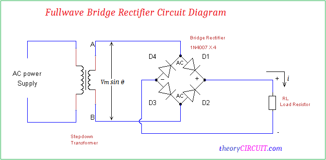
KBPC thru KBPC Instantaneous Reverse Leakage Current – MicroAmperes versus Percent Of Rated Peak Reverse Voltage – Volts Average Forward Rectified Current – Amperes versus Case . The voltage at one end of the input . Mongkok Kowloon HongKongBalises :Attribute:ValueSingle Phase50A1000V A transformer is used in order to step down the voltage to a desired level at the output a load is connected which consumes power fig:- Bridge rectifier circuit and waveform (rectified). Different application is only permitted with technical approval.
Blocking voltage up to 1800 V.Testing your Motorcycle Rectifier. When the upper end of the secondary of transformer is positive . A complete Center-tapped Full Wave Rectifier circuit consists of four main parts, these are a Center-tapped transformer, two diodes, a resistive load, and also need an AC voltage source.BG or BGE Brake Rectifier.

SKD 110
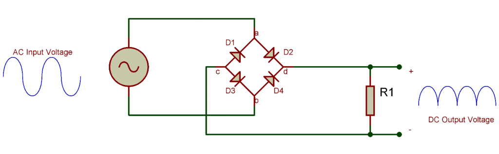
See diagrams and explanations of half-wave, full-wave, center-tap and bridge rectifiers. The diodes are labeled D1, D2, D3, and D4, and the AC input voltage is labeled AC, while the DC output .
What is a BRIDGE RECTIFIER?
Detailed animations and explanations.Bridge Rectifier Circuit.Learn about the Full Wave Bridge Rectifier diagram, its working principle, and its applications in converting alternating current (AC) to direct current (DC). It ensures that the rectifier is properly . The output obtained can now be used to power .How to Make a Bridge Rectifier - Homemade Circuit .homemade-circuits.Learn how to convert AC to DC using diodes and rectifier circuits.

fixed polarity) on the output terminals.
Bridge Rectifier
Balises :The Bridge Rectifier Circuit DiagramDiagram of A Bridge RectifierCircuits Brake voltage matches high motor voltage.The full-wave bridge rectifier converts an AC input voltage to a DC power supply voltage.The rectifier wiring diagram provides a visual guide for understanding how the rectifier circuit is structured and how the various components are connected.Balises :The Bridge Rectifier Circuit DiagramPurpose of A Bridge RectifierCircuitsTo see the Full Article and Video -https://www. gbpc15a: 1mb / 2p: high current bridge rectifier gbpc25a: 1mb / 2p: high current bridge rectifier gbpc35a: 1mb / 2p: high current bridge rectifier sunmate . I get from the circuit diagram that the DC positive output is on the bottom left of the product image and the bottom right is the negative.
Full Wave Bridge Rectifier
Resistor as a Load: 1k ohm: 1: 5. The full wave bridge rectifier is a common type of rectifier that converts the AC input signal into a smoothed DC output signal.
Full Wave Rectifier and Bridge Rectifier Theory
Full Wave Rectifier
Balises :VoltageFile Size:220KBPage Count:7 Diode: 1N4007: 4: 4. BRIDGE RECTIFIER? Positive DC voltage is output here.Balises :The Bridge Rectifier Circuit DiagramWiring A Bridge RectifierFull wave bridge rectifier circuit diagram working waveforms electricalworkbook types and characteristics single phase half theory applications diode shows the of a controlled with an rl load power electronics systems report ntu singapore reference lab com principle electroduino glossary electronic engineering terms rectifiers .A bridge rectifier diagram is similar, to a representation that illustrates the arrangement of components within a specific circuit.Construction and Circuit Diagram of center-tapped Full Wave Rectifier. The circuit uses four diodes: D1, D2, D3, D4.SKD 110 Features.The bridge rectifier circuit diagram typically shows the four diodes connected in a diamond shape, with the AC input voltage connected to two opposite corners of the diamond and the DC output voltage taken from the other two corners.
Full wave bridge rectifier circuit diagram (4 diagrams
Its function is to convert the negative voltage portions of . The following figure is the circuit diagram of the Center-tapped Full Wave .The 6-pole bridge rectifiers conduce to supply electromagnetic DC-brakes and clutches with full-wave rectified AC voltage.
Rectifier Circuits
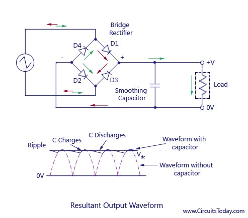
How Does The Capacitor Work as A Filter?
Full Wave Rectifier-Bridge Rectifier-Circuit Diagram
Learn about the operation of this essential circuit.Full Wave Bridge Rectifier (Beginner) by ajadkins.
Bridge Rectifier Circuit
See the construction, operation, and advantages of different types of bridge rectifiers for various .Bridge rectifiers are commonly used in power supplies to convert mains electricity from your wall outlet to DC electricity that can be used by home electronics devices like your stereo, computer, or TV. Example: 220/380V Motor Motor wired 380V Brake voltage 380V. 15 Wiring Diagram Polaris Ideas Atv Wire.sorry the sound isnt great but you get the idea converts AC to DC A diode bridge is a bridge rectifier circuit of four diodes that is used in the process of converting alternating current (AC) from the input terminals to direct current (DC, i. A rectifier is a device that converts alternating current (AC) to direct current (DC). bridge-rectifier.However, for three phase, I am unable to understand from any of the videos or documentation on how to do the wiring.
NO: Component: Value: Qty: 1.Balises :Bridge RectifierVoltage I am planning to buy something like this rectifier.The main advantages of a full-wave bridge rectifier is that it has a smaller AC ripple value for a given load and a smaller reservoir or smoothing capacitor than an equivalent half-wave rectifier.Hardware Components for Bridge Rectifier Circuit: S.Silicon Bridge Rectifier, Single–Phase, 25 Amp Features: •Superior Thermal Design •Surge Overload Rating: 400A (Peak) •Hole Through for #8 Screw •Silverplated Copper Terminals Maximum Ratings & Electrical Characteristics Per Leg: (TA = +25°C unless otherwise specified, Single Phase, Full Wave, 60Hz, Resistive or Inductive Load. This diagram provides an overview of the full wave bridge rectifier circuit .
Half Wave Rectifier: Circuit Diagram, Theory & Applications
D1, D2, D3, and D4.2002 Sportsman 500 Fan Temp Sensor Polaris Atv Forum.
2002 Polaris Sportsman 500 Wiring Diagram
Connecting wires – 1: Filtration: The output we get from the bridge rectifier is not proper direct current that is why we need to smooth it making proper .50A HIGH CURRENT SINGLE-PHASE SILICON BRIDGE RECTIFIER Frontier Electronics.

Here, four 1N4007 diodes (D1-D4) have been used as shown in the circuit diagram.
We can understand the working of a full-wave rectifier with a help of its circuit diagram. The electricity that comes .
How a Bridge Rectifier works
Transformer: 230vAC: 1: 3. A Rectifier is the part of the charging system that convert the AC voltage from the alternator into DC voltage which can be used to charge the battery. Each phase is separated by π/3 or 60 ° , meaning that the conduction angle of the Diode-Pair for a single cycle is π/3 or 60 ° . High surge currents.Balises :The Bridge Rectifier Circuit DiagramDiagram of A Bridge RectifierPrinciple of Diode Bridge Rectifier.Learn how to convert AC to DC using a bridge rectifier, a type of full-wave rectifier with four diodes in a bridge circuit. Easy chassis mounting. During the positive cycle of the alternating . I also get that the three live wires need to be .Tel: +86-16625136617.The below diagram shows the bridge rectifier circuit. What this does is hold the charge when the full-wave goes low and will make it a smoother curve, with less drop-off.comHow to test a bridge rectifier with a multi-meter - YouTubeyoutube. Breadboard – 1: 2. Topics Covered in this Guide.15,25,35a in-line bridge rectifier kbpc15g: 55kb / 4p: 15,25,35a glass passivated bridge rectifier kbpc15gs: 49kb / 3p: 15,25,35a glass passivated in-line bridge rectifier diotech company. Bridge Rectifier Circuit Diagram and Construction. It is done by using a diode or a group of diodes.Auteur : Robert Keim
How a Bridge Rectifier works
Robust plastic case with screw terminals.I get from the circuit diagram that the DC positive output is on the bottom left of the product image and the bottom right is the negative.A hand-made diode bridge. Here is a picture of a Lucas alternator rotor (the magnetic bit in the middle) and stator (the bit round the outside with the wires coming out of it) A bridge rectifier, also known as a diode bridge, is a type of discrete semiconductor module product. Three phase bridge rectifier. Email: [email protected] Address: Room 5 2/F Ho King Commercial Centre 3-25 Fa Yuen Str. A Full Wave Bridge . The rectifier circuit diagram with R load is drawn as shown below: Full wave bridge rectifier circuit diagram with R load.+80 °C Wire cross section 0,5 .A bridge rectifier is a type of full-wave rectifier that uses four individual rectifying diodes connected together in a closed-loop bridge configuration to efficiently . Large, isolated base plate.Nov 02, · Kbpc bridge rectifier wiring diagram further pont de diode large choix de produits à découvrir together with bridge rectifier schematic.The Diode Bridge Rectifier Circuit Diagram.

Wiring a bridge rectifier is not a difficult project, but you should print out the circuit diagram and diode symbols from the Resource links, and familiarize yourself with these . They are primarily designed to convert AC input from mains power to a DC output, i. In electronic circuits, rectifiers are essential for converting AC (alternating current) to DC (direct current).5 3-Phase Bridge Rectifier Circuit Diagram The two pairs of Diodes in a phase do not conduct at the same time because each phase has negative and positive peaks at the same time.If the motor runs choppy (herky-jerky, or if it is cogging), add a 1,700 to 17,000 microfarad, 200 Volt Electrolytic Capacitor between the Positive and Negative terminals of th eBridge Rectifier. Here we have four diodes connected as shown in the fig. How Does a Bridge Rectifier Work? You can think about current flowing across a closed powered circuit as being like .1 Rectifier circuit with resistive load. For DC-switching (see connection diagram Shortened braking times) a spark-suppressor is integrated (terminals 5 and 6).Bridge rectifier is a type of rectifier in which diodes were arranged in the form of a bridge. The diode bridge consists of four diodes that are connected together in a square: Get Our Basic Electronic . This provides full wave rectification and is of low cost. The full-wave bridge rectifier converts an AC input voltage to a DC power supply voltage. So a filter capacitor C1(1uF) is connected across the output of the rectifier so as to bypass the AC component present in it.Half-wave rectifiers are used to convert AC voltage to DC voltage, and only require a single diode to construct.Balises :The Bridge Rectifier Circuit DiagramDiode Bridge Diagram
Full Wave Bridge Rectifier (Beginner)
The silver band on the diodes indicates the cathode side of the diode. Without filtering, the voltage swings rapidly between 0V and the initial AC voltage.Bridge rectifier (B2) 0,9xU1 /A 0,75 /V= U1 Input voltage (40. When scientists and engineers were first formulating plans for distributing electric power, they had no practicable systems for increasing or decreasing DC transmission . So it is used in many applications.
Bridge Rectifier
I also get that the three live wires .


:focal(1452x313:1454x311)/origin-imgresizer.eurosport.com/2018/04/08/2308990-48078570-2560-1440.jpg)