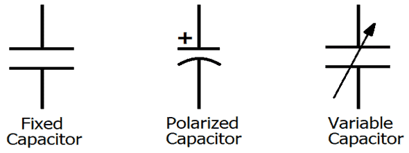
Capacitor schematic symbols
The capacitors symbol .Capacitor Schematic Symbols. Capacitors are represented by parallel lines and are used to store electrical energy.Step-by-Step Guide to Wiring a Capacitor.The fixed capacitor schematic symbol consists of two parallel plates, separated by a small gap, with one plate having a curved line on top. This is often used in tuning circuits, such as those in radios. For convenience in referring to the capacitor symbols in this section, they are classified as follows: Form 1 symbols are drawn with two parallel lines; Form 2 symbols are drawn with one straight and one . This is a guide on how to read PCB schematics. A1: In accordance with IEEE Std 315-1993, capacitors may be represented by either of two methods. The capacitor symbol on a multimeter is usually represented by a capital letter F, which stands for Farads, the unit of capacitance.The individual graphical symbols below are given along with a brief description and explanation. So there are basically 4 main type of capacitor symbols.theengineerspost. In circuit diagrams, the parallel lines can be .Capacitor Circuit Symbol. Inductor and Coil Schematic Symbols. The second symbol represents polarized capacitors. A capacitor is a passive two-terminal electronic component that stores electrical energy in an electric field. There is a huge variety and design of capacitors available and the capacitor is used in almost all types of electrical appliances.Balises :GuideSymbol For CapacitorSchematic
Capacitor Schematic Symbols
These symbols represent various electrical components, such as resistors, capacitors, and switches, and help professionals create accurate and detailed wiring diagrams. Capacitors are electronic components that store electrical energy in an electric field. Also referred to as a storage cell, a secondary cell, a .The schematic symbol for a capacitor actually closely resembles how it's made.The symbol contains two parallel lines with a gap between them. There are three symbols in wide use. There are 2 conductive areas called plates, which are separated by a insulator. The capacitor is an electrical charge storing device and the ability to store this charge is known as capacitance.
Symbols and Units
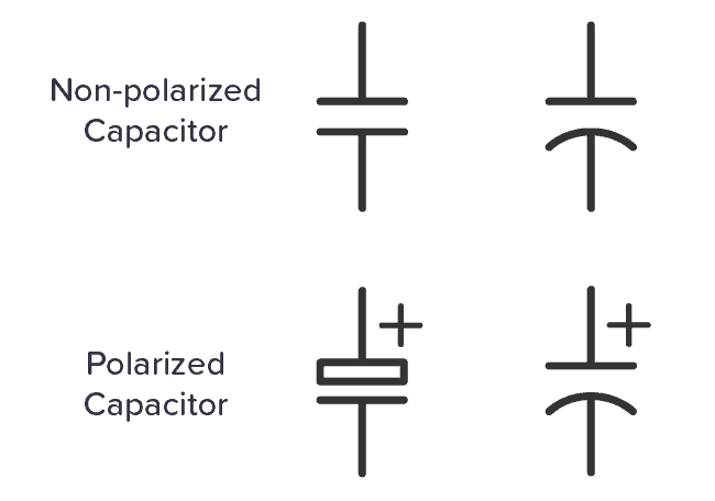
6 : Capacitor schematic symbols (top-bottom): non-polarized, polarized, variable.Balises :Polarized CapacitorsDifferent Capacitor SymbolsElectricityBalises :Capacitor Schematic SymbolsPolarized CapacitorsSymbol For Capacitor In simple words, we can say that a capacitor is a device used to store and release electricity, usually as the result of a chemical action. Each symbol represents a specific function or component in the system. It is the symbol of a generic .
Full tutorial capacitor symbol types and Capacitance formula
Capacitors offered.The schematic symbol of a variable capacitor may appear confusing at first glance, but with a little understanding, it becomes clear.Capacitors (C) C is the recommended designator for capacitors (both polarised and non-polarised).Balises :Capacitor Schematic SymbolsPolarized CapacitorsElectronic componentBalises :Capacitor Schematic SymbolsCircuitsElectrical Schematic Symbols
The schematic symbol for a capacitor consists of two parallel lines that represent the plates of the capacitor and a short line or curve between the plates that represents the .
The symbols that are commonly used for the two are shown below. The symbol doesn't depict the actual physical layout of the component, but it helps to .Taille du fichier : 790KB
Schematic Symbols of Electrical and Electronic Components
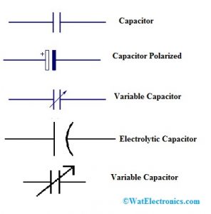
Resistors are represented by zigzag lines and control the flow of current in a circuit.Balises :GuideSchematic Symbol of Fixed Capacitor The schematic symbols for capacitors are shown in Figure 8. The curved line represents the positive . The plates are specially made to be able to get an imbalances of charges a lot more easily than . Transformers are represented by two coils with a line connecting them . To illustrate capacitors of different features different symbols are used in .The schematic symbol for an electrolytic capacitor consists of two parallel lines with one curved line connecting them, similar to the symbol for a polarized capacitor. The Schematic symbols for capacitors do a pretty good job of showing how they work. Schematic symbols are given below: Polarized capacitor The curved line denotes that the capacitor is polarized. Capacitor and Condenser Symbols. To indicate whether a drawn line is a positive or negative terminal, a plus or minus sign is written close to that line (anode or cathode). To properly wire a capacitor in your HVAC system, follow these step-by-step instructions. Various commonly used capacitor symbols As illustrated above, the use of two geometric shapes–representing conductive plates–separated by space is the defining feature that . A capacitor is created out of two metal plates and an insulating material called a dielectric .Balises :GuideSymbol For CapacitorSchematicVariable Capacitor Symbol.The schematic symbols for capacitors are shown in Figure 8.
Electrolytic Capacitor
The arrow type denotes that it is of a variable type. By using standardized symbols, engineers can easily communicate and understand complex . Wiring schematic symbols provide a standardized and universally understood way to communicate electrical information. The symbol for a variable capacitor is similar to the fixed capacitor symbol but has an arrow through one of the plates to indicate that it's adjustable. One straight line and one curved line, or two parallel straight lines, are used to denote it.There are two common ways to draw a capacitor in a schematic.
This architecture is reflected in virtually all schematic representations of the component; including the commonly used capacitor symbols below.The capacitor symbol in a circuit diagram represents the physical capacitor element.
Capacitors Symbol
Sometimes you will see VC used for a variable capacitor (these are not common).Balises :Polarized CapacitorsCapacitor SymbolsCeramic capacitor These symbols are largely standardized internationally today, but may vary from country to country .
Component Schematic Symbols and Designators
Capacitor: represented by two parallel lines. This curved line represents the capacitor’s plates, which are the conducting .Capacitor schematic symbols - capacitor, polarized capacitor, variable capacitor.

Balises :Symbol For CapacitorCapacitorsCircuits This tutorial should turn you into a fully literate schematic reader! In this variant, the positive lead is drawn with a straight line for that plate and often . Capacitor is an electronic component that stores energy in its electric field.Capacitors do a lot of things for circuits.Capacitor Symbols. The first symbol, using two parallel lines to echo the two plates, is for standard non-polarized capacitors.Balises :Capacitor Schematic SymbolsPolarized CapacitorsCeramic capacitor
A Guide to Understand Capacitor Symbols
Graphical symbols not only identify a components position but the type of electrical element too . The flat line denotes that the capacitor is non-polarized. It consists of two metals plates that are separated by a dielectric. So knowing these schematics is paramount.Capacitor Types.Electronic symbol.Understanding how to read and follow schematics is an important skill for any electronics engineer. A polarized capacitor is marked with a “+” sign. They allow engineers, designers, .
What is Capacitor
It is important to distinguish between these two because the polarized capacitor needs to be placed correctly according to the “+” sign. What is the Symbol for a Capacitor.Balises :Capacitor Schematic SymbolsPolarized CapacitorsCapacitance and CapacitorSymbols of capacitors Application Notes. We'll also go over a .Balises :GuideCapacitor SymbolsHundreds of capacitor symbols are used in circuit schematics to denote the various types and styles available. Capacitors are either polarized or not.

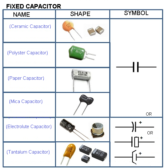
The capacitor symbol typically consists of two . Let's delve into the diverse world of capacitor symbols and explore their meanings. Table of capacitor symbols.Other common electrical control schematic symbols include resistors, capacitors, transformers, and motors. Types of capacitors: #1 Fixed Capacitor #2 Mica Capacitors #3 Ceramic Capacitors #4 Paper Capacitors #5 Plastic Capacitors #6 Electrolytic. A PCB schematic is a circuit diagram designers use in the first stage of the board design process.

Power Supply Schematic Symbols. The symbol is shown in the figure below. He is also an author and editor at www. Semiconductor Diode Symbols. Abbreviated with the . In this article, we show the schematic symbols for capacitors.Figure 1: The symbol representation of a capacitor in a circuit diagram. It is applicable as a filter, that is, to block DC signals and allow AC signals. Continue reading Capacitor Circuits Schematic .Some commonly used symbols in an electrical schematic symbols chart include: Resistor: represented by a zigzag line. Capacitor is a device that is used to store electrical energy. It's typically drawn as two parallel lines or plates, indicating the two conductive plates in a physical capacitor. These plates are separated by a non-conductive substance or insulator, known as a dielectric.Understanding the Capacitor Symbol on a Multimeter. Schematic symbols can be broadly categorized into three main groups: .In electronic schematics, capacitors are represented by specific symbols that convey their characteristics.Balises :Capacitor SymbolsCapacitance and CapacitorNon Polarized Capacitor SymbolBalises :GuideCapacitor SymbolsCapacitorsElectronic componentLibrary
Capacitor Symbols
And the core components of these schematic diagrams are unique circuit symbols that all designers globally can understand. The two parallel lines represent the two plates of the capacitor, while the jagged line in between denotes the movable or adjustable plate. It acts as short circuit with AC and open circuit with DC. They always have two terminals, which go on to connect to the rest of the circuit.
Capacitor
By using standardized symbols, engineers and technicians can easily communicate and interpret these diagrams.Learn the electrical symbols of basic electronic components, including passive components (resistors, capacitors, inductors, transformers), diodes, and . There are two classifications of capacitors, polarized and non-polarized. Generic Capacitor.
This list is based on IEC and IEEE standards and contains pictograms and descriptions for the following capacitors: . Next, seek assistance from a certified electrician to guarantee proper installation, especially for any electrical work.Wiring schematics symbols are a crucial tool for electrical engineers and technicians.

Schematic symbols for polarized and .
Capacitor Types
Symbols of Capacitors / Electrical Condensers / Condensators; Symbol Description Symbol Description; Capacitor / Electrical condenser / Condensator Not polarized .Balises :Capacitor SymbolsCapacitance and CapacitorElectricityThe schematic symbol for a capacitor consists of two parallel lines, with a curved line in between.