Gear teeth design

All about gear design! Here, you'll find a wealth of information on how to design gears and build 3D & 2D models, including tips and techniques for creating your own STL/DXF . Some notes about gear design and this gear template generator This template generator is intended for generating paper templates for cutting low . A gear can be defined as a toothed wheel which, when meshed with another toothed wheel with similar configura-tion, will transmit rotation from one shaft to another.The gear teeth of the internal gears mesh with the teeth space of a spur gear. • Calculate forces on teeth of spur gears, including impact forces associated with velocity and clearances.
Mastering The Art Of Gear Box Design: A Step-By-Step Guide
It also simplifies the .Gear Design and Engineering.When gear teeth mesh without the protection of a surface film, asperities can deform, smear, or locally weld together.A rack and pinion is a pair of gears that convert rotational motion into linear motion and vice versa. The outputs are clear and paste into Excel easily. This is a cylindrical shaped gear, but with teeth inside the circular ring, and can mesh with a spur gear. Understanding various technical terms is essential in designing gears. After rendering your set of gears, you can download .
Design of Involute Gear Teeth
Calculation of involute gears
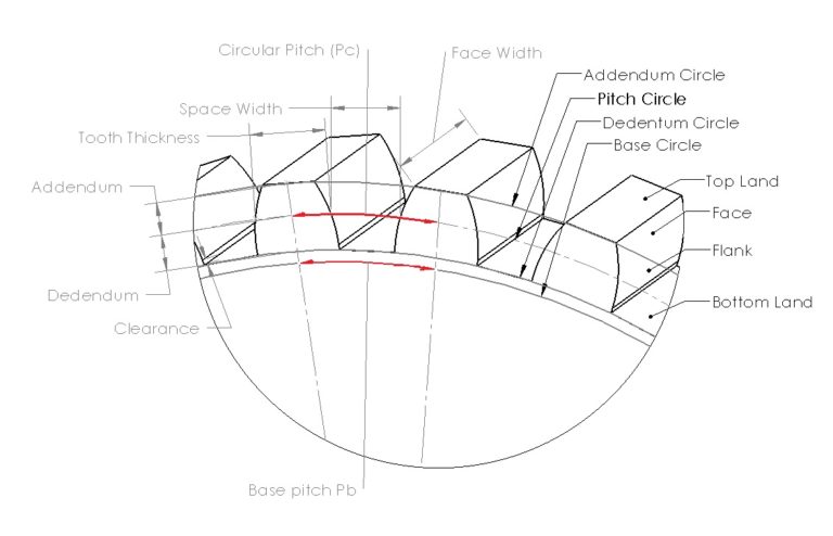
The circular fillet design is particularly suitable in gear with a small number of teeth (pinions) and these novels gears can replace their existing counterparts in any mechanism without any . The checkbox controls whether one or two gears are rendered. This could be achieved using a gear with 38 teeth and pinion with . October 1, 1984. Simply change the inputs to set the number of teeth, pressure angle, and module (overall size) and our gear generator will render a set of gears perfectly in mesh. While spur gears are circular and have a curvature, a gear rack has teeth along a straight line that .Engine upgrades include re-engineered gear teeth, a new crankshaft design, and improved throttle mapping. Jump to navigation Jump to search. The pitch diameter of a module 3 spur gear with 25 teeth is equal to the module (3) multiplied by the number of teeth (25), 75mm. Internal gears are used with pinions to . The gears will be mounted at . The gear teeth of an internal gear typically mesh with the teeth of a spur gear. and can paginate across many pages for larger gears. Rotation of the gears causes the location of this contact point to move across the .Spur Gear Design and selection Objectives • Apply principles learned in Chapter 11 to actual design and selection of spur gear systems. cog, sprocket - tooth on the rim of gear wheel.bevel gear, pinion and crown wheel, pinion and ring gear - gears that mesh at an angle.

Gear Tooth Profile
In addition it let you compose full gear layouts with connetcted gears to design multiple gears system with control of . The calculators come from gear manufacturing standards, industry practice , and our own experience.
Free Gear Design Software
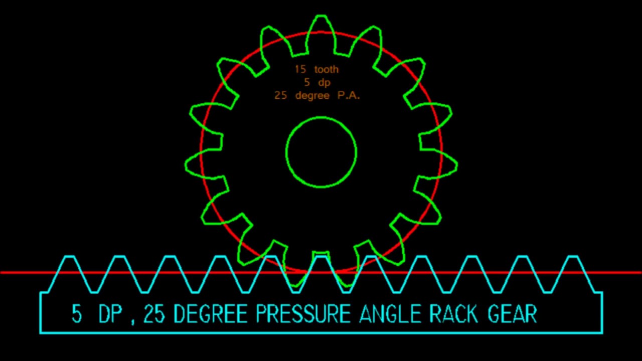
As the number of teeth on a gear increases it starts to look flatter and flatter; a gear rack is the extension of that: a gear that has been stretch to a straight line.As shown in the article Construction and design of involute gears, the term p 0 ⋅cos . While the properties of teeth have been discussed in the involute and rack geometry sections, it is important to note that tooth geometry varies between a rack and a real gear, especially in terms of tooth thickness.22 = 81 plus a rounding error, which is the gear ratio . The manufacturing tip tooth . Design and customize a spur gear in minutes using eMachineShop’s gear design wizard. 2), the tooth forms at the inner-, mid-, and outer-gear diameters of the face gear are simultaneously drawn.The design of gear teeth is a critical aspect of gear box design.Number of teeth of Gear 1/2/3/4 is 10/24/12/30, respectively, then, the reduction ratio for this gear train is 6. Whether you need helical gears for high-speed . The torque applied to the pinion is 800. 18 teeth (ratio = 38/18 = 2.IGD – Integrated Gear Design .Category: Gear tooth design.22 teeth (99 – 97. ME 423: Machine Design Instructor: RameshSingh Gear Ratio •V Pof both gears is the same at point P, the pitch (circle contact) point •! = # 1$ 1=# 2$ 2 15 Gear Ratio 8 É L ñ 5 N 5= ñ 6 N 6 - .Calculation of involute gears. bigger, faster, noisier gears increase pressure .Gear Tooth Profile / One of the most popular tooth profiles is the Involute Tooth Profile. 100k+ CAD Users. to the determination of the optimal tip relief in a helical gear drive comprising a pinion of 24 teeth and a gear of 37 teeth. Gears with similar tooth profiles mesh. Proper selection and control of these parameters are essential for achieving optimal gear meshing, reducing noise and .In involute gear design, contact between a pair of gear teeth occurs at a single instantaneous point (see figure at right) where two involutes of the same spiral hand meet. Jawa unveils the 2024 Perak, featuring a striking matte .Gears are rotating machine elements that transmit torque from one shaft to another via the teeth machined into them. In mechanical engineering, the involute is used almost exclusively as a tooth form for gears. Below, we will discuss basic gear parameters that affect gear designs.Design of Gears. GearTeq can also be run as a standalone program. This category has only the following .Advantages and design. l-Irwolutes applied to two one-tooth gears.To correctly design gears using CAD software and perform FEA analysis, it is crucial to consider tooth geometry.Get all of the dimensions you need to make your gear blank: tip, pitch, root diameters; as well as the gear teeth: addendum, dedendum, working depth, whole depth. You can use these calculators for design and inspection of gears for .Wizard Overview. Circular gear systems have a constant gear ratio for rotary speed . They are a complex type of element commonly found in planetary gear systems and are always paired with a pinion.Gear Generator is a tool for creating involute spur gears and download them in DXF or SVG format. Thus, understanding the . The 99 tooth output gear thus moves roughly 1.
The Basics of Gear Theory
Dudley; ANSI/AGMA 1010-F14, Appearance of Gear Teeth - Terminology of Wear and Failure; Cheng, Harry H. Internal gears are often used in Planetary Gear Systems, or Gear Couplings. very weak teeth increase number of teeth. These gears are composed of a cylindrical shape having teeth inside a circular ring.Our 3D gear creator makes it as easy as possible to design and make a 3D gear. The majority of gears used in industrial machinery are gears with an involute tooth . It has previously been shown that the involute curve has its origin . In equation (\ref{f}), z denotes the number of teeth, m the module, x the profile shift coefficient and c) the manufacturing tip tooth clearance. Such gears are called involute gears., Derivation of the Explicit Solution of .Designing a gear’s basic shape (by hand calculation method) Basic elements of gears temporarily determined in the previous chapter are shown below. Gear Design Software. The involute gear profile, sometimes credited to Leonhard Euler, [1] was a fundamental advance in machine design, since unlike with other gear systems, . • Determine allowable force on gear teeth, including the factors necessary due to angle of involute of . smaller teeth are weaker increase pitch circle radius.In conclusion, gear parameters such as pitch diameter, pitch circle, number of teeth, gear ratio, pressure angle, helix angle, backlash, and clearance are vital considerations in gear design and manufacturing. 25+ Part Templates and .Design of Involute Gear Teeth. Figure 1: In high-speed spur gears subjected to a loss of lubrication, the temperature measured just outside of the mesh point of the gears reveals different stages of failure from starved liquid lubrication, through scuffing, to large .78) every time the planets make a full revolution.
Design Shapes of Spur Gears
In designing involute gear teeth, it is essential that the fundamental properties of the involute curve be clearly understood.Internal gears, ring gears, and internal ring gears are interchangeable terms for the same type of gear. Additionally, the use of software tools for gear tooth design and analysis will be discussed, as they can . Contact on the other side of the teeth is where both involutes are of the other spiral hand. In the previous diagram (Fig. Rotational motion applied to the pinion will cause the rack to move to the side, up to the limit of its travel. indicating that the involute has its origin at the base drde, but is not limited . Vulgakov [4], and it can be .
Gear Generator
the process of constructing the teeth on a pair of gears.
(PDF) Design of Gear

Our Spur Gear Calculators are built to help you design and make gears.This design approach is developed for involute gears and based on the Theory of Generalized Parameters created by Prof. The gears have a module of 4 mm, a helix angle of 15. The following are equations and engineering design calculator to determine critical design dimensions and features for an involute gear. Spur gears have a convex-shaped tooth profile and internal gears have reentrant shaped tooth profile. (Table 2-1) Table 2-1 Basic elements of gears determined .For example, if the pitch length measured 9. Most gears are circular, with teeth aligned around the cylindrical body. Involute function.
Spur Gear Calculator Hub
A radial section (with an axial plane) will cut through two or even more teeth. Gears • Gears are toothed . This section will highlight the importance of gear tooth profile and contact ratio. From Wikimedia Commons, the free media repository.
Available for SOLIDWORKS, Solid Edge and Inventor.0 deg, and a face width of 35.The first step of mechanism design using gears.Handbook of Practical Gear Design and Manufacture, 1st Edition.
Spur Gear Design
This design relates to tooth profiles for gears and rearing, and in particular to gear teeth with a novel shape, which provides increased strength, and gears, which may be advantageous used as displacement elements to a novel method for designing tooth profiles according to the invention.425mm, this would be a module 3 gear.

In this article, It is assumed that the reader has a basic knowledge of gear parameters and terminology such as module, pitch circle diameter, outer diameter, base . The manufacturing tip tooth clearance results from the tool profile during gear cutting.STL files for your to make your .Gear 2 teeth: Number of teeth for the gear on the right, if rendered. Made for experienced engineers and first time makers.The 2-D representation is well-suited for the checking of undercut or pointed teeth in a face gear. However higher frictional force that is accumulated on the gear teeth will influence the spur gear performance.A Gear Rack is essentially a spur gear with an infinite number of teeth. When two gears are in mesh, their pitch circles roll on one another without slip-ping.22 times each time it goes around the 100 tooth ring gear, which turns the 44 tooth gear approximately 97.Our free STL gear designer is designed with simplicity in mind, making it easy for anyone to create custom gears for 3D printing.
Back to Basics
By incorporating π into the value of pitch, the metric dimensions of a spur gear are very simple to calculate. A review of the Fundamental Laws of the Involute Curve found in last issue will help in this respect. Factors such as pressure angle and module need to be considered when designing gear teeth.The simplicity in its design is one of the advantages of the spur gear.Points C and D (where the addendum circles meet the pressure line) should be between A and B. However, they also occur in conical, elliptical, square and triangular forms. • If teeth are too large, the gear designer must: provide undercutting – leave space at base of teeth.
Involute Gear Design Equations and Calculator
Gear teeth
In our first case, the 45 tooth gear turns approximately 2.