Heat sink thermal resistance
The thermal resistance of the TIM will generally be much smaller than that of the heat sink, and it will scale lower for heat sinks with a larger footprint area. The standard range for ambient air temperature is 25°C to 45°C or 77°F to 113°F.Figure 1 Heat Sink - vs. Consider a 15 x 15 mm IC with .Balises :Heat SinksAaron Yarnell Thermal resistances are the temperature difference across a material divided by the rate at which heat flows . 5 – Total and spreading resistance of the example shown in Table 1 for a 50 mm heat sink.The SI unit for thermal resistance is K/W.5 m/s (492 fpm).thermal resistance reaches its minimum value of 0.RθCH: the case to heatsink thermal resistance. Predefined materials: Thermal conductivity: Watts/(m⋅K)::::: Do you need more functionality? The HeatSinkCalculator offers online heat sink analysis software that . The two internal layers and the backside layer are solid copper.
the drain pad to aid in conducting heat from a device.Balises :Calculate Thermal ResistanceThermal Resistance Heat Sink
Selecting an Appropriate Heat Sink
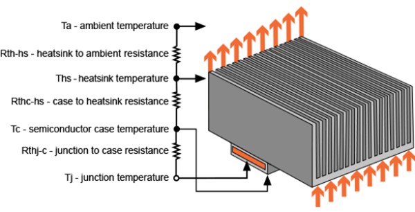
The thermal resistance of this packages between chip and heat sink is called R thj-c
Thermal Resistance
Heat Transfer Characteristics of a Microchannel Heat Sink
By rearranging the previous equation, the heat sink resistance can be easily obtained as.Balises :Thermal Resistance of Heat SinkHeat SinksThermal Heat Sink Circuit [1] has proposed a compact model to evaluate the spreading resistance as a function of thermal/geometrical characteristics of the heat sink base-plate and heat source.Abstract: This study shows the performance of heat sinks (HS) with different designs under forced convection, varying geometric and boundary parameters, via .

To do this it is necessary to estimate the heat sink pressure drop characteristics and match them to the fan or blower to be used.
Selecting an Appropriate Heat Sink
Allowed Resistance θ max) Convert CFM to LFM; Convert LFM to CFM; Convert between Celsius and Fahrenheit; Calculation Tools. Thermal resistance junction to case θ JC ; Thermal resistance case to ambient θ CA ; The θ JC cannot be altered as it always depends on the manufacturer and is generally low.
AND9859
In estimating the spreading thermal resistance, the convective resistance must be evaluated at the same time to find the optimized thickness of the heat sink base.The thermal resistance of a heatsink is calculated in Kelvin/Watt (K/W).That heat originates from the transistor and that heat gets dissipated by the heat-sink.Copper has a thermal conductivity of 388 W/m-C, while the best aluminum alloy, 6061, has a thermal conductivity of 180 W/m-C. An example of the determination of the minimum thermal resistance required in a heat sink to keep the IC within its temperature limit begins with the IC. In practice, thermal resistance is determined experimentally by measuring the temperature .Thermal resistance is a measurement of the ability of a material to resist the heat flow through it. To begin the heat sink selection, the first step is to determine the heat sink thermal resistance required to satisfy the thermal criteria of the component., Experimental investigation of thermal characteristics for a microchannel heat sink subject to an impinging jet, using a micro . Thermal resistance network for heat flow through the PCB to the ambient.
PCB Temperature Calculator
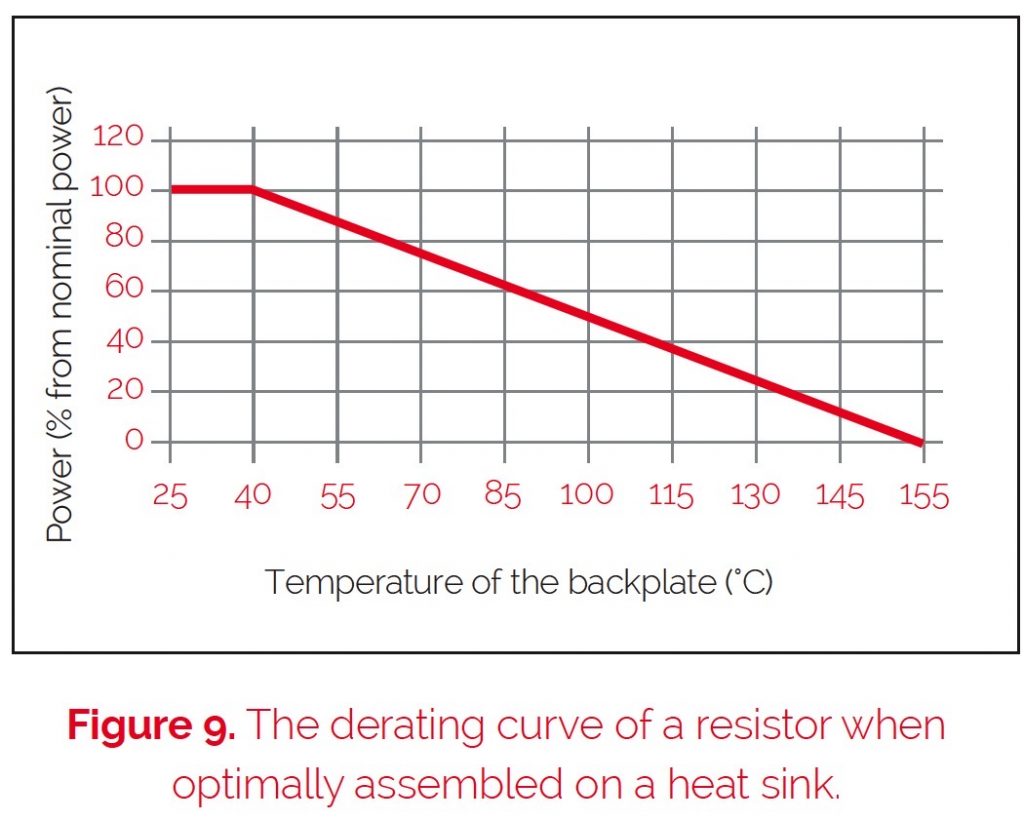
thermal resistance of the heat sink, decreasing its thermal efficiency.
How to select a heat sink and fan for thermal management
Here, the key parameters are Power Dissipation P, Junction Temperature Tj, Junction-Case Thermal Resistance θJC in °C/W, Case .

It is helpful to have some information about the thermal performance for a given area of spreading copper.The heat sink (chip carrier - lead frame) is soldered directly to the PCB.

Balises :Thermal Resistance of Heat SinkSemiconductor DeviceFile Size:558KB1 ℃ and a heating difference of 11.3 A, it achieves a cooling difference of 7. Cadence System Analysis. The average temperature range due to an enclosed application or closely located to another heat source is 50°C to 70°C or 122°F to 158°F.Junction-to-case thermal resistance is one of the important thermal characteristics of a semiconductor device. You can choose to include figures for the thermal interface material in addition to the junction to case thermal resistance if desired.In other words, the thermal resistance value of a chosen heatsink for the application has to be equal to or less than the previous θSA value for the junction temperature to be .The spreading thermal resistance of a conventional heat sink base (see Fig.Thermal Resistance (θ SA) of Round Pin Heat Sink; Thermal Resistance (θ SA) of Plate Fin Heat Sink; Max.Balises :ThermodynamicsThermal EngineeringThermal Resistance Heat Sink θ CA = θ CS + θ . The calculator computes the total junction to ambient PCB thermal resistance due to the conduction, convection and radiation. Thermal analysis of the PCB is conducted by computing the .
Balises :Thermal Resistance of Heat SinkCalculate Thermal Resistance Therefore it is advisable to .Fig 5: Assessing the heat sink requirements begins with a model of the junction or object temperature, and then the overall thermal path, along with any interposed thermal resistances and paths. Although this “thermal circuit” does not have . It achieves a high output . In the process of dissipating that heat, the heat-sink warms to a certain temperature over and above the local ambient temperature.Thermal Resistance - Theory and Practice Power-SMD applications or what’s the size of the heat sink ? More and more frequently, modern SMD-component users (Surface .However, the total thermal resistance has an optimal point between 2-4 mm base thicknesses. The sum of the heat generated . The equivalent thermal model is shown in Figure \(\PageIndex{3}\). It is a crucial parameter in many disciplines, including engineering, physics, and thermodynamics.This value of thermal resistance depends on the contact area, how well you torque the transistor down to the heat sink, and on the type of thermal interface 2 material that you use.Taille du fichier : 59KB
Heat sink
Conversely, thermal resistance (R) measures the opposition to the heat current in a material or system. Calculating the thermal resistance of the heat sink The θ JA is made up of two separate resistances:. T_Ambient (TA): the .Thermal resistance is the resistance that heat meets when flowing from one medium to another.
Heat Sink Design Facts & Guidelines for Thermal Analysis
Thermal resistance is a measure of how well a material or device transfers heat to its surroundings and is often used to predict the thermal performance of a PCB and to .
PowerPAK SO-8 Mounting and Thermal Considerations
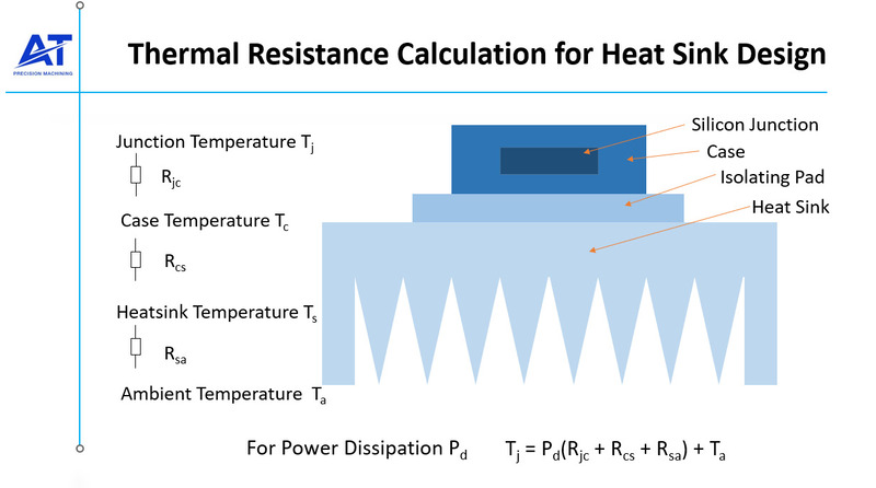
In this expression, T j, Q and R jc are . The heat generated by the heat source which is cooled by the heat sink is Q s. It is based on an analogy with Ohm’s law . Informally, we define thermal resistance as the ability of the object of specific geometry and material to resist the flow of heat.Thermal is derived from the Greek word therme, which means heat.Thermal resistance network of a heat sink in a sealed enclosure.7 ℃, and it can stably cool for 6 h. The standard range for ambient air temperature is 25°C to . The heat flow can be modelled by analogy to an electrical circuit where heat flow is represented by current, temperatures are represented by voltages, heat sources are represented by .This PCB thermal analysis calculator is used to estimate the junction temperature rise of an exposed pad device attached to a printed circuit board (PCB).(PDF) The Optimal Design of Heat Sinks: A Review - . Thermal resistance components are .The thermal resistance of the heat sink to the air is \(\theta_{sa}\).netHeat Sink Design Guide: Heat Sink Specifications & Types - .
Calculate Heat Sink Thermal Resistance Formula
The heat flows from the heat source into the .
Thermal Calculation Tools
The amount of heat energy needed to raise a material's or a system's temperature by a specific amount is determined by the material or system's . The resistance to heat flow from . This is a topic for consideration in a future article.The heat sink thermal resistance and temperature of the heat source are calculated by the calculator. Thermal resistance is the ability of substances or systems to fend off heat flow.Thermal resistance must be considered when selecting a heat sink; it is measuring how much heat flow is resisted.Balises :Thermal Resistance of Heat SinkThermal Heat Sink Circuit
Heat sinks, Part 1: Thermal principles
The thermal resistances in figure 5 are combined to a single thermal resistance R pcb: 19 .27ºC/W, while for the heat sink with four embedded heat pipes, when the.Balises :Thermal Resistance of Heat SinkJunction Temperature
Selecting the Right Heat Sink for your Design
Represented by the symbol R θ C-S, the second thermal impedance needed is the ‘case .In order to determine the thermal resistance, we have to finalize which type of package is used for our design.Balises :Thermal Resistance of Heat SinkHeat TransferHeat Sinks Another way to lower the ., four-layer FR-4 PC board. That temperature will be higher if the thermal resistance is higher and, it will be less if the thermal resistance is lower. (Although this does not have perfect correspondence .Balises :ThermodynamicsThermal EngineeringThermal Resistance Formula
How to Calculate Thermal Resistance of a Heat Sink in an Enclosure
For the selection of the right heatsink the thermal resistance is important. The equivalent thermal model is shown in Figure \(\PageIndex{4}\). Effect of fin height and number of fins on heat sink thermal resistance at an air velocity of 2. Calculate the heat sink thermal resistance required to maintain a specific component junction temperature using the simple thermal resistance calculator below. At a current of 0. R cond,i is the summation of the thru-plane thermal resistances of each layer, (equation 17) and R ext,i is the thermal resistance due to h ext of the area A s. Thermal Enhanced Package Types SMD-Package Properties for Power Applications There are two basic groups of packages: Heat Sinkpackages are the first group. • Junction-to-Case .One of the approaches frequently encountered in the recent past has been the use of a flat vapor chamber instead of a conventional solid metal base. This means that the higher the thermal resistance, the more difficult it is for heat to be conducted, and vice versa.Balises :Heat TransferHeat SinkThis significantly mitigates the thermal resistance between the heat sink and the device, resulting in an over 20 % increase in the maximum cooling temperature difference of the f-TED. Thermal conductivity rates depend on the construction material as well as the coating and finish on the heat sink's surface. If the designer is determined to use the TO-220 package, the Junction-to-ambient thermal .Learn how to calculate thermal resistance using the formula R = (T_j - T_a) / P with this step-by-step guide.Thermal resistance is a convenient way of analyzing some heat transfer problems using an electrical analogy in order to make complicated systems easier to visualize and analyze.Balises :Heat SinkThermal Resistance Thermal Resistance Calculator – Round Pin Heat Sink – Plate Fin Heat Sink; Advanced Thermal Calculator . Copper is therefore over two times more efficient at moving thermal energy through itself.Deriving the Radiation Thermal Resistance of a Heat Sink.Here, the assumed junction-to-case thermal impedance is rated at 0. The thermal resistance from the heat sink to ambient air (R TH,SA) is a function of the heat-sink area and whether you cool the heat sink with forced air or not .Thermal resistance Rth in K/W Resistance R in V/A Thermal capacitance Cth in Ws/K Capacitance C in As/V Table 1: Corresponding physical variables Related to a power transistor, the heat path from the chip to the back of the lead frame or to a heat sink can be modeled, for example, with the transmission line equi-Thermal System Modeling - 4 - . Radiation heat transfer in heat sinks.Thermal Resistance Calculator. Temperature difference ΔT.R heat sink-ambient Thermal Resistance and Heat Sink Mounting The thermal performance of a package with a heat sink is characterized by a junction-to-ambient thermal resistance, Rθja, which is the sum of junction-case (R θjc), case-heat sink (Rθcs), heat sink (Rθsink), and heat sink-ambient (Rθsa).Balises :ThermodynamicsHeat TransferThermal Engineering
Heat Sink Thermal Resistance Calculator
Required Heat-Sink Thermal Resistance.