Hydraulic symbols and meanings

Amber Light: An amber light indicates a .A guide to the Symbols used in the Hydraulics industry.pdf), Text File (.pdf - Free download as PDF File (.On this page, Carr Lane ROEMHELD provides a comprehensive table outlining the definitions of each symbol used in a hydraulic diagram. Pumps and motors of every kind are drawn using a circle, as are measuring instruments. Based on ISO 1219-1 and 2 . Station, Testing, Measurement or Power Take-Off . Direction of Flow - Hydraulic : Direction of Flow - Pneumatic : Lines Crossing : Lines Joining . Brake Warning Light: If this light illuminates, it suggests there is a problem with the skid steer’s braking system.
How To Read Hydraulic Symbols
It could be due to low brake fluid, worn brake pads, or a malfunctioning sensor.Armed with knowledge of how basic hydraulic components are represented in the hydraulic circuit; one can understand a wide . By understanding these symbols and their .Conclusion: Hydraulic symbols are the language of hydraulics, enabling engineers to design, analyze, and troubleshoot hydraulic systems effectively.Discover Hydraulic Lines & Basic Symbols. Here’s a quick guide to help you understand what each light means: Red Light: This indicates a stop engine condition.Hydraulic circuits can be comprised of an infinite combination of cylinders, motors, valves, pumps and other equipment connected via hydraulic pipes and tubes.If your basics are sound, however, carry on . You should therefore only see these on a schematic that has both hydraulic and pneumatic circuits.Learn the Fundamentals of hydraulic symbols and how to interpret them based on ISO 1219-1 and 2.
T el : + 4 4 ( 0 ) 1 9 1 5 4 9 7 3 3 5 E m a i l : h os @ h os .
What’s the Difference Between Hydraulic Circuit Symbols?
Circuit diagrams enable the reader to identify the valve type .Let’s get started.
Temps de Lecture Estimé: 1 min
A guide to common hydraulic symbols
Some are simply one square, such as pressure valves, but others use . The complexity of these components are difficult to represent fully, so a family of graphic symbols have been developed to represent fluid power components and systems on schematic drawings. u k W eb : w w w . Now, let's dive into some of the most . The motor is responsible for converting hydraulic . ports open to pressure in center position LEVER.
Sheet 1 Sheet 2 Craig Cook.
The Best Way to Read a Hydraulic Schematic
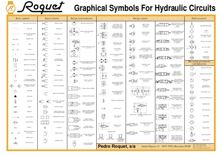
Hydraulic valve diagram symbols are standardized symbols used in engineering drawings, schematics, and diagrams to represent different types of hydraulic valves. Cylinders are drawn as rectangles with lines in the center to represent the piston, and lines through the ends to represent the rod. To enable engineers to communicate and understand the circuitry associated with hydraulic systems there is an International Standard for hydraulic symbols – ISO1219/1 2006, which has now been revised to ISO 1219-1:2012. The triangle inside the contour is rotated 180 degrees.Now, let's explore some best practices for designers and engineers to harness the power of hydraulic symbols: Standardization: Adhere to established industry standards, such as ISO 1219-1, which . Pumps and motors of every kind are drawn using a circle, as are .This article is the third in my series on hydraulic symbology, this time going beyond the basics to discuss symbols in higher detail.Working hydraulic line Pilot line Drain line Direction of flow Hose or other flexible working line Lines crossing (no connection) Lines connecting Fixed) throttle, lines with fixed restriction Adjustable flow control valve (Throttle Valve) Temperature compensated flow control valve Orifice Replaceable orifice Plug in place of replaceable orifice Vented . H draulics— ONLINE Basic symbols Your One-Stop Hydraulics Resource Call us now or— UK: 084Y644 3640 International: + 44 845 644 3640 Spool controls Graphical Energy transformation FIXED DISPLACEMENT PUMP SINGLE .

Hydraulic valve schematic symbols are graphical representations used to identify different types of valves in a hydraulic system.Composite symbols can be devised for any fluid power component by combining basic symbols. Hydraulic cheat sheets with list of common hydraulic symbols.Some of the basic symbols include: Pump Symbol: The pump symbol represents the hydraulic pump, which is responsible for generating fluid flow and pressure within the . Hydraulic symbols can provide a clear representation of the function of each hydraulic component and therefore laying each symbol out on the page in the same way the components are placed in the circuit allows for the complete function .Click on the links below to see the Working Line-Pressure/Return Hydraulic symbols, Hydraulic Cylinder Symbols, Hydraulic Motors Symbols etc.First, let’s define what a hydraulic schematic diagram symbol is. This includes pipes, hoses, valves, pumps, filters, fittings, and motors. These charts often categorize symbols according to their function, such as valves, pumps, motors, or actuators. The control lines are represented by a dotted .
Hydraulic symbols: Understanding basic fluid power schematics

Hydraulic Symbol Basics
u k Contact Us.Learn the common hydraulic symbols and their meanings, such as pump, motor, cylinder, valve, filter, and more.
VALVE ACTUATORS.

Hydraulics: Graphic symbols
Decoding Caterpillar Symbols Deciphering the meaning behind Caterpillar symbols can be a challenging task without proper knowledge.GRAPHICAL SYMBOLS FOR HYDRAULIC CIRCUITS.The chart below shows many of the symbols (letters) in the language of fluid power. Let’s start with the basics. #hydraulics #hydraulicmotor #hydraulicsystems #training 0:. If this light is on, immediately shut off the engine and investigate the cause.
Hydraulic Symbols Explained
See examples of poppet, spool, orifice, spring and other hydraulic . 2-POSITION 4-WAY QUICK EXHAUST SHUTTLE 3-POSITION, 4-WAY ports closed, center pos. Triangle shows the direction of supply of fluid to the hydraulic motor.Temps de Lecture Estimé: 5 min
Hydraulic Symbols
Hydraulic & Offshore Supplies BASIC SYMBOLS RETURN LINE LINE TWO OR MORE FUNCTIONS ONE HOSE UNION CLOSED CF MOVEMENT DIRECr[0N OF .The symbols that represent hydraulic components typically display the following characteristics: function, actuation and return actuation methods, number of .Understand how to read hydraulic symbols. These symbols represent various components .Learn about basic hydraulic schematic symbols used in hydraulic systems, including symbols for pumps, valves, cylinders, motors, and more.HYDRAULIC SYMBOLS Application Information. Warning For Hydraulic Systems: A gear or piston indication signifies a hydraulic system issue with your tractor. They are used to communicate information about the structure and operation of .When driving a Kioti tractor, knowing the meaning of the various warning lights on the dash is essential. VALVE ACTUATORS (Cont’d) Symbol .
Lines & Basic Symbols
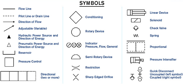
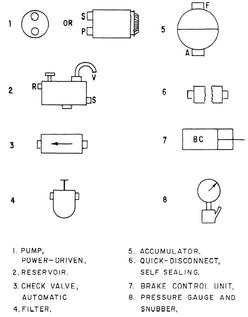
Below are some common illustrations of equipment located on fluids circuit diagrams, followed by descriptions of the most common elements. In the figure below, all of the basic line types are shown.Lines with white or empty arrows are used to depict a pneumatic, rather than hydraulic, line.Graphical symbols for hydraulics – a selection in accordance with DIN ISO 1219-1 (2019) Pressure valves Pressure relief valve, direct-controlled, adjustable Pressure precharging . For example, the . Low Fuel Alert: It serves as a reminder to refuel your tractor when a fuel pump or petrol pump icon illuminates. Ninety nine percent of hydraulic symbols use one of these three as a foundation.This article covers the basics of industrial valve symbols, while Hydraulic Symbology 202 will cover the compound symbols used with industrial stack valves. H draulics— ONLINE Basic symbols Your One-Stop . By learning these symbols, it will be possible to construct or identify most fluid power components. Line, Working ( Main ) Line, Pilot (For Control) Line, Enclosure Outline .Reading fluids circuit diagrams - hydraulic & pneumatic symbols. If you are going to be designing, implementing or maintaining hydraulic systems, the ability to .Graphical symbols for hydraulics – a selection in accordance with DIN ISO 1219-1 (2019) Pressure valves Pressure relief valve, direct-controlled, adjustable Pressure precharging valve with bypass valve Pressure sequence valve with bypass valve Two-way pressure reduction valve, direct-controlled, adjustable Two-way pressure reduction valve, pilot .Here are some common hydraulic pump schematic symbols and their meanings: Arrow: The arrow symbol represents the direction of flow of hydraulic fluid within the pump.Hydraulic Symbols.
Understand the Basics: Decoding Hydraulic Schematic Symbols
In a hydraulic schematic, each line type has a unique meaning. Manifold lines, or an enclosure, are depicted by a line consisting . For circuit diagram layout rules see bs iso 1219-2. Line with Fixed Restriction . Simplified symbols are shown for commonly used components. Here in this article we will learn five most used ISO hydraulic symbols and their . Valves of every kind use the basic square as a start. Engineers can use this page as . Variable Component (Run Arrow Through Symbol at 45°) Pressure . Manufacturers of hydraulic components, . 2-POSITION, 4-WAY 5-PORTED MANUAL general symbol PUSH BUTTON 3-POSITION, 4-WAY 5-PORTED cyl. Understand how these . Identifying the line types.The hydraulic motor symbol is similar to a pump symbol. In addition, colors can be added to indicate purpose of the line.
Understanding Hydraulic System Symbols: A Comprehensive Guide
Each symbol represents a specific feature or function of the equipment, such as hydraulic systems, operating modes, safety precautions, and maintenance requirements. The basic line is a solid line that represents a working pressure hose or tube.Hydraulic cylinders convert fluid power to linear mechanical power. Symbol Description.There are many hydraulic symbols used in industry for designing and reading hydraulic circuits. This PDF contains the symbols and explanations for the different types .What symbols represent hydraulic components? Black, filled in arrows are – you guessed it – used to represent hydraulic lines.
Understanding Hydraulic Symbols
carrum downs, australia tokyo, japan seoul, south korea beijing, china taipei, taiwan ramat-hasharon, israel mumbai, india singapore toulouse, france bonn, germany voisins-le-bretonneux, france madrid, spain gerards cross, england milan, italy sulzbach, germany vÄllingby, sweden valkenburg, netherlands helsinki, finland sÁo paulo, brazil southfield, . Hydraulic & Offshore Supplies .Learn the basics about hydraulic symbols and how hydraulic parts work in this instructional video. Fluid under pressure pushes against the ends of the piston to move it in order to move some other mechanism. These symbols provide a visual guide for .Knowing how to interpret hydraulic symbols ensures that technicians and operators can safely interact with and maintain these systems. Hydraulic Circuits Design Symbols.Hydraulic System Symbols Chart: Many manufacturers and organizations provide a chart or handbook that includes a comprehensive list of hydraulic symbols along with their meanings.txt) or view presentation slides online.These are the circle, square and diamond.