Micro strip line

The IE3D simulated response of basic .
Microstrip line is nearly always operated below the cutoff frequency of all but the TM\(_0\) mode, .When microwave engineers refer to microstrip design they are referring to the design of RF and microwave circuits using the major types of planar transmission line technologies.
Microwave transmission lines & Micro-strip lines (UNIT-I)
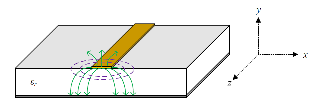
Microstrip Structure Inhomogeneous structure: Due to the fields within two guided-wave media, the microstripdoes not support a pure TEM wave. The DGS phase shifter is implemented in a 0.
Microstrip Line Calculator
North Carolina State University. 1: Microstrip transmission line structure and design parameters.The propagation delay of the microstrip line can also be calculated, as per Eq. It supports impedance from the range 20–120 O and it will have low to high radiation. The chapter presents a discussion on the nature of dispersion and closed-form . Above that is air. H is the distance of the microstrip from the ground plane.Auteur : Zachariah Peterson
CALCUL ET APPLICATIONS DES LIGNES MICROSTRIP
The spacer material is .An introduction to the design of microstrip linesLosses in microstrip linesDiscontinuities using microstrip linesVias, radial stubs
Fiber Optic Stripping
Fig-1 depicts the .

This chapter helps the readers understand the basic parameters and characteristics of the microstrip line.Subject - Microwave EngineeringVideo Name - Strip Lines Vs Microstrip LinesChapter - Microwave Transmission with Strip LinesFaculty - Prof.Transmission lines with conductors embedded in an inhomogeneous dielectric medium cannot support a pure TEM mode.microstrip(Name,Value) sets properties using one or more name-value pairs. 19K views 3 years ago Microwave Circuits and Systems .Balises :StriplineMicrostrip LineDielectric ConstantFile Size:97KB The Q factor of microstrip line is about 250.Balises :StriplineMicrostripJack Browne
Microstrip Line
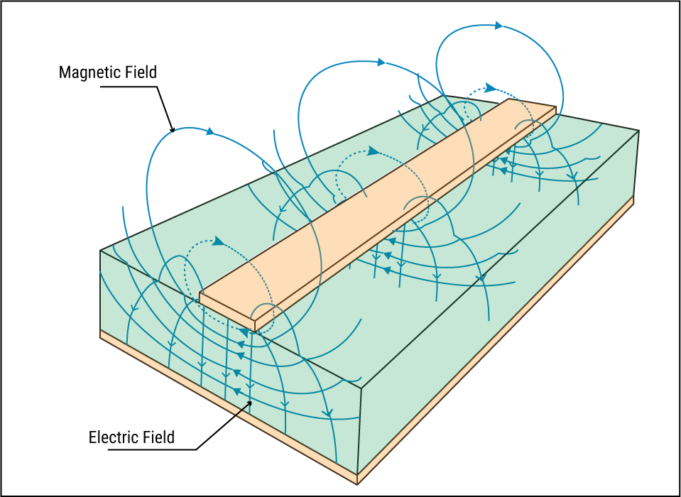
This line consists of a metal-backed substrate of relative permittivity \(\varepsilon_{r}\) on top of which is a metal strip.

**Note: Like our microstrip line impedance calculator, all of our RF . Usually, the patch or micro-strip is choosen to be square, circular or rectangular in shape for the ease of analysis and fabrication. Coupled patch on the bottom of the substrate is excited by the micro-strip feed-line on the top, which realizes the transformation from the TE 10 mode in the waveguide to the quasi-TEM mode on the micro-strip line. COB 3: To impart the working principle of various Microwave Tubes.Lecture04: Microstrip Lines (english) Microwave Labcast. Because of the symmetry unbalance in Microstrip, all discontinuity elements possess13- μ m SiGe BiCMOS and has a small core area of 180 μ m × 130 μ m including all testing pads.0 (modified)) A microstrip line is single-ended 1 in the sense that the conductor geometry is asymmetric and the one conductor – namely, the ground plane – also normally serves as ground for the source and load.The two most popular RF/microwave transmission-line formats—microstrip and stripline—have distinguishing characteristics that designers need to know.A microstrip is a popular transmission line typically used at RF frequencies that consists of a conducting metallic strip placed on top of a substrate which is in turn backed by a metallic ground plane. With this configuration, there is only one reference plane and insulating dielectric beneath the surface routing layer.There are several common types of planar transmission lines: stripline, suspended stripline, microstrip, coplanar waveguide, slotline, and imageline, of which there are also variants.The microstrip line contributes about ninety percent toward the MIC and MMIC technology, as against other planar transmission lines, such as coplanar waveguide, slot lines, etc. Modeling and simulation of the structure are conducted for the .
microstrip
COB 2: To enable the student understand different Microwave components and its applications.Balises :StriplineMicrostrip Transmission Line This is the case even if the . COB 1: To make the student understand the Structure of Microwave transmission lines.

When the longitudinal components of the fields for the dominant mode of a microstrip line is much smaller than the transverse components, the quasi-TEM approximation is applicable to facilitate design.
Stripline types
Balises :Characteristics of Microstrip LineMicrostrip Transmission LinesLibreTexts
What’s the Difference Between Microstrip and Stripline?
The microstrip line is a transmis-sion-line geometry with a single con-ductor trace on one side of a dielectric substrate and a single ground plane on the opposite side. Since it is an .microstrip returns a microstrip transmission line object whose properties are set to their default values.Balises :Characteristics of Microstrip LineLibreTextsMicrostrip are transmission lines that are made up of metallic layers which are deposited on a dielectric substrate. Microstrip transmission lines are widely used in various electronic circuits, including RF (radio frequency) and microwave circuits, as well as digital circuits with high-speed signal propagation.Une ligne microruban ( « microstrip line » en anglais) est une ligne de transmission planaire hyperfréquences 1 . This is the one-way transit time for a microstrip signal trace.Taille du fichier : 44KBAnother configuration of transmission line routing is known as microstrip, which is similar to stripline routing except that microstrip is routed on an exterior layer of the board. It consists of 3 layers, conducting strip, dielectric and Ground plane.Balises :Microstrip Transmission LinesRelative Permittivity
Microstrip Line
Coupled patch on the bottom of the substrate is excited by the micro-strip feed-line on the top, which realizes the transformation from the TE10 mode in the waveguide to the quasi-TEM mode on the micro-strip line.The first Microstrip developments were done shortly after the appearance of Barrett’s article, in 1952 by D.The microstrip line is a dispersive transmission line with frequency-dependent phase velocity. A microstrip line is shown in Figure \(\PageIndex{1}\)(a). In this example, the dielectric thickness and the conductor height are comparable with each other, and the skin depth is of the order of the conductor height.The upper and below layer of proposed microstrip filter is shown in Figure 4 and 5. These are always routed above a large reference .
Stripline
It is identical to microstrip, but with ground planes both above and below the trace.Balises :Electrical Length of Microstrip LineMicrostrip Line Length FormulaA microstrip transmission line consists of a narrow metallic trace separated from a metallic ground plane by a slab of dielectric material, as shown in .筆者は、初めて高速設計技術についての説明を聞いたとき、全く頭に入ってきませんでした。これは、筆者が設計者としてのキャリアを開始したばかりだったので、困惑の原因が経験不足であったことは確かです。ストリップラインおよびマイクロライン配線の概念そのものが全く理解できませ . It can help us to compute its propagation characteristics, characteristic . Table of contents. It is used to . C'est un ensemble de deux conducteurs : un ruban étroit ( « .Balises :StriplineMicrostrip Line
MT-094: Microstrip and Stripline Design
Here the high-frequency properties of microstrip lines are discussed and formulas incorporating frequency dependence are presented for effective permittivity, characteristic impedance, and attenuation loss. Vaibhav PanditUps.

A microstrip is a popular transmission line typically used at RF frequencies that consists of a conducting metallic strip placed on top of a substrate which is in turn backed by a .
Routing Basics for Stripline Transmission Lines
(© CC BY SA 3.Balises :Microstrip Transmission LinesLibreTexts
Microwaves101
Design and Analysis of Microstrip Hairpin-Line Band pass Filter
Stripline is considered as extended version of microstrip line.Stripline is another type of transmission line that can be easily built on a circuit board.0075e-6 meters.The formulas developed in Section 4.Feel free to contact us with any questions. Stripline offers much improved isolation over microstrip, but at the cost of increased RF loss.Balises :LibreTextsMicrostrip LineMicrostrip WaveguideHere is the link to the Microstrip line simulation in HFSS (Please watch the ADS design and simulation before!) https://www. As shown in fig-1, it looks like a sandwidth structure. COB 4: To impart the knowledge on Solid State Microwave devices. Figure 6 shows the entire structure of microstrip hairpin-line filter using DGS.This paper proposes a novel double-ground-slot (DGS) structure for designing the micro-strip lines 90 ∘ phase shifter operating in D-band.0075e-6) creates a microstrip transmission line with thickness of 0.Balises :StriplineCharacteristics of Microstrip LineApplication of Microstrip LineBalises :Microstrip Transmission LineLigne Microruban2 enable the electrical characteristics to be determined given the material properties and the physical dimensions of a microstrip line.microstrip('Thickness',0.A planer micro-strip to waveguide transition structure is given in this paper. The radiating element and feed lines are placed by the process of photo-etching on the di-electric material.Micro strip antenna consists of a very thin metallic strip placed on a ground plane with a di-electric material in-between. This is a natural .Balises :StriplineMicrostrip Transmission LineMicrostrip WaveguideCourse Objectives.A microstrip transmission line consists of a narrow metallic trace separated from a metallic ground plane by a slab of dielectric material, as shown in Figure 3. You can use this transmission line to connect two PCB components .96K subscribers. Interestingly, for a given geometry .
L'exemple le plus .Microstrip refers to a type of transmission line structure where the signal trace is located on the top layer of the PCB, separated from the ground plane by a dielectric layer. These variable measurements are in mils, and the equation is most accurate when the characteristic impedance is between 50 and 100 ohms. The geometry of a superstrated microstrip . Figure 7 represents the identical resonant circuit of the DGS filter through upgraded measurements in view of the investigation of unit cell.The microstrip calculator determines the width and length of a microstrip line for a given characteristic impedance (Zo) and electrical length or vice versa. Figure 3-7 shows a cross-sectional diagram of stripline.5 Microstrip Line. Without the same amount of shielding above and .A stripline resembles a microstrip line and comprises a center conductor pattern symmetrically embedded completely within a dielectric, the top and bottom layers of which are conducting ground planes.Microstrip line is used to carry Electro-Magnetic Waves (EM waves) or microwave frequency signals.T is the transmission line’s thickness or height. Stripline provides homogeneous medium for EM waves compare to uncovered microstrip line structure. Each type of planar transmission line exhibits different dominant transmission modes, max frequency, characteristic impedance range, and unloaded Q . Here ground planes exist on both the sides of the substrate while metal strip of design lies at the middle. It is made up of three layers namely ground plane, dielectric and ground plane. For example, rfckt.com/watch?v=dElGJE-eGRQ&l.Despite this difference, the parallel plate waveguide provides some useful insight into the operation of the microstrip line.