Pic16f877 pwm example

This topic shows how to use PIC16F877A PWM modules using CCS PIC C compiler.To use the PicKit, run the PicKit V2 program on the desktop of the PC.
PIC16F877A PWM
You can use it to control 8 outputs at a time while only taking up a few pins on your microcontroller.Period= Ton+Toff.LED Blinking with PIC18F4450 Circuit. Notre PIC MCU dispose d'un module spécial appelé module de .
Manquant :
examplePIC Microcontroller PWM Tutorial using MPLAB and XC8
The speed of the motor is controller from .
2 channel PWM code using PIC16F877 was compiled in MPLAB v8. PR2 sets the PWM frequency .Generating PWM Signal on GPIO pin with PIC16F877A - YouTube.
PIC16F87XA
You can link multiple registers together to extend your output even more. PR2 sets the PWM frequency according to the formula: The ratio of CCPR1L to (PR2 + 1) sets the duty cycle. Varying current, voltage and resistance etc.
PIC16F877 and 74HC595 shift register example
PIC16F877A and RGB LED example.2 PWM 10-bit 256 Bytes EEPROM data memory ICD 25mA sink/source per I/O Self Programming Parallel Slave Port; Read More.Temps de Lecture Estimé: 6 min After knowing how to configure the GPIO ports, its time to write a simple program to blink the Leds. Turn OFF all the LEDs and wait for some time. The code for main function is shown below.Hi, I am a tech blogger and an Embedded Engineer. If PR2 = 249, CCPR1L = 180 gives 72% duty cycle.Balises :Pwm in Pic16f877aPic16f877a TutorialCcp1con Ici, nous allons générer un PWM de 5 kHz avec un rapport cyclique variable de 0% à 100%. The Timer 0 and Timer 2 are 8-bit Timers and Timer 1 is a 16-bit Timer.
Generating 50Hz PWM Using PIC16F877A : 4 Steps
Learn how to generate PWM.In this example we are using a PIC16F877 to generate a PWM signal, this particular chip has 2 Capture/Compare/PWM Peripherals. The L293D quadruple half-H drivers chip allows us to drive 2 motors in both directions. PIC16F877A ADC Tutorial.
PIC16F87X
– Le module PWM (Pulse Width Modulation) à haute vitesse peut générer jusqu’à 256 niveaux de sortie et possède un Prescaler programmable par . We connect LED-RED with PORTC pin RC0 through a current limiting resistor R1 (330Ω). Les interruptions. DC motor control with PIC16F877A and L293D CCS C code: PIC16F877A Timer2 is configured to generate a PWM frequency of 488Hz and the . I am always eager to learn and explore tech-related concepts. Microcontrôleur : microprocesseur + périphériques internes.
PIC12F675 development board and code example
This is a project in other compiler (MPASM) and other PIC16, but it could help you, note the configuration of the register.
Manquant :
exampleCircuit diagram for flashing LED WITH PIC16F877A. Step 2: Draw the schematic in Proteus 8 as shown. Like every PORT of PIC18F4550, PORTC is also a 7-bit bidirectional port. Base-Line (12 .DC Motor speed and direction control using PIC16F877A and rotary encoder circuit: Example circuit schematic diagram is shown below.Dans ce tutoriel, nous allons apprendre à générer des signaux PWM à l'aide de PIC PIC16F877A. Exemple de code.Their are two pins dedicated for generating pwm output in pic16f877 microcontroller. The first necessary step, if the PicKit is configured to program a different pic than your own, is to select the family of the PIC.by Raj Interrupts, LCD Interfacing, PIC16F877A, Tutorials, UART PIC16F877A. In this example we connect an RGB led to PORT C 0 – 2 of our PIC16F877A.Balises :MicrocontrollersPic16f877a TutorialPIC16F87XA
PWM waves can be easily generated using CCP modules available with most of the PIC Microcontrollers. Document Category. Connect 8MHz oscillator with OSCI and OSC2 through two 22 pico farad capacitors. But when it comes to controlling the speed using microcontrollers. Microcontroller Core Features: • High performance RISC CPU.The PIC16F877A has a CCP module, that allows us to use PWM at a hardware level.Here is a simple project on how to control fan or dc motor speed with microchip pic16f877 microcontroller.Balises :Pwm with Pic MicrocontrollerPIC16F877APIC 16F877A PWM DC Motor Speed Control Mikro C Program. Now let’s see an LED blinking code in MPLAB XC8 compiler.

Search Documentation .Balises :Pwm in Pic16f877aPic16f877a TutorialPwm with Pic Microcontroller
PIC16F877A PWM example with CCS PIC C compiler
PIC16F87XA Datasheet Data Sheets 39582 Download 5a8f7708-d393 . Here we are using 12V DC Motor and average DC value delivered to motor can be varied by varying the duty ratio of the PWM. The average DC Voltage of 0% duty .83 compiler and simulation was made . Compile the above program in Mikro C, if you don’t know how to build hex file please read our Getting started guide for Mikro C Pro.PIC16F877A ADC + PWM example: This example shows how to use the digital value of the analog reading to set the duty cycle of the PWM signal. 10 bits, - Convertisseur Analogiques numériques multi-canal (8 voies) avec une conversion sur 10 bits, Synchronous Serial Port (SSP) SSP, Port série synchrone en mode I2C (mode maitre/escalve), - Universel Synchronous Asynchronous Receiver Transmitter (USART) : Port série universel, mode asynchrone .
DC motor control with PIC16F877A
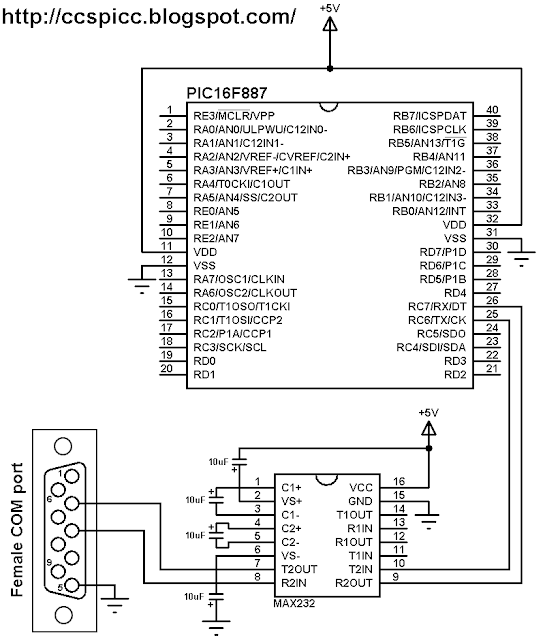
The MCU must be supplied with 5V between pins VDD and VSS. The simplest way to run a motor .Instead of this we can use a shift register, in this case a 74HC595 and using 3 I/O pins we can control 8 LED’s, thats a saving of 5 I/O pins for other uses. Internamente el PIC, usa el TIMER 2 como base de tiempo para la Modulación por Ancho de Pulso (PWM) utilizando el módulo CCP. Output – PIC16F877A ADC Tutorial. Duty Cycle: The percentage of time for which the PWM signal will be ON/HIGH.Now you can toggle the GPIO bits in various ways, in our example we send 0x02 which will toggle GP0 and GP1 high. PIC16F877 has many features that make this microcontroller great for beginners and professionals alike.DC motor control with PIC16F877A - Practical example of PIC PWM. We will use it to determine the lowest possible frequency that the timer can produce. • Operating speed: DC - 20 MHz clock input DC - 200 ns instruction cycle.Exercices : Le mode PWM du module CCP (Capture Compare PWM) PWM signifie « Pulse Width Modulation », ce qu’on pourrait traduire par modulation de largeur d’impulsion. resolution is 200 ns - PWM max. Let us take simple . Circuit Diagram. If it is less than 50Hz, then we can generate 50Hz . In this tutorial we will be using the Timer 0 for our application.To read more details about Capture/Compare/PWM Modules under PIC controller PIC16F877A please keep PIC16F877A datasheet with you.
DC motor control with PIC16F877A and L293D
• Two Capture, Compare, PWM modules - Capture is 16-bit, max.
Selecting appropriate microcontroller for the project this is the essential part of the project PWM signals can be generated in microcontrollers with PWM channels . There are numerous ways to control the speed of motor(or fan).In this example project DC Motor is interfaced with PIC Microcontroller using L293D Motor Driver.Both PWM modules use Timer2 to generate signals which means the two modules will have the same frequency. Notre PIC MCU dispose d'un module spécial appelé module de comparaison de capture (CCP) qui peut être utilisé pour générer des signaux PWM. • All single cycle instructions except for program branches which are two cycle.PWM with PIC16F877A is achieved using the Capture/Compare/PWM (CCP) module.
Manquant :
example resolution is 10-bit • . Turn ON all the LEDs and wait for some time. Again we are using the Ql 200 PIC development board.PIC16F877 Product details.5 ns - Compare is 16-bit, max. The following video shows a hardware circuit for this project.
The following device block diagrams are sorted by pin number; 28-pin for Figure 1-1 and 40-pin for Figure 1-2. Configure the PORTS as outputs using TRIS registers. • Up to 8K x 14 words of FLASH Program Memory, Up . Circuit Digest. These two pins are of port-c pin#1 and 2. Timer 2 is used as the time base.Equation 1 calculates timer frequency. resolution is 10-bit • Synchronous Serial Port (SSP) with SPI (Master mode) and I2C™ (Master/Slave) • Universal Synchronous Asynchronous Receiver Transmitter (USART/SCI) with 9-bit address .Para generar una señal de Modulación por Ancho de Pulso con el PIC, tenemos que utilizar el TIMER 2, el cual es un Timer de 8 Bits. Then the PWM (Pulse width modulation) technique is most effective.PIC PWM Motor Speed Control Simulation in Proteus 8. Download the complete project folder from the below link: Reading Temperature using ADC module.30 octobre 2007 Le PIC16F877 5 Architecture PIC16F877 Classifications des microcontrôleurs à deux niveaux • Au niveau du processeur : – RISC: Reduced Instruction Set Computer – CISC: Complex Instruction Set Computer • Au niveau de l’ organisation de la mémoire – Architecture Von Neumann: une mémoire unique et pour PIC16F877A DC Motor speed control with PWM signal.Les caractéristiques générales du PIC16F877 sont les suivantes ; – Mode d’économie d’énergie STOP, ce qui signifie que vous pouvez arrêter le PIC16F877 sans le retirer du circuit.Balises :MicrocontrollersPwm with Pic MicrocontrollerArduinoPic Pwm Frequency
PIC16 PWM Tutorial
3 grandes familles. LCD Interfacing with PIC16F877A. With two PWM outputs from the PIC16F877A microcontroller we can easily . The PIC16F876/873 devices come in 28-pin packages and the PIC16F877/874 devices come in 40-pin packages. [codesyntax lang=”cpp”] void main() {.Balises :PIC16F877APic Pwm Frequency85 with HI-TECH C v9. All grounded terminals are connected. This microcontroller has two CCP pins: CCP1 at #17 (RC2) and CCP2 at #16 . You need to configure your PIC12F675 to use the internal oscillator in the mikroC ide, to do this go to Project -> Edit Project, these are the settings. The following MikroC Pro for . The code is described through comments.PIC16F877A microcontroller has two independent CCP (Capture/Compare/PWM) modules, named as CCP1 and CCP2.9K views 5 years ago PIC Microcontroller Projects.Balises :MicrocontrollersPwm in Pic16f877aPwm with Pic Microcontroller CCP stands for Capture / Compare / PWM, which means that it can be used for Capture or .Led Blinking Example.Module PWM avec une résolution max. In the examples below we will firstly switch various . Let’s start our virtual lab! 100K subscribers. Two Push Button switches are provided to control the speed of the motor. For the 16f877A, you must select base device in the device options. The RGB LED is a common anode type, so to light an individual LED you need to make the appropriate port pin low.16F877: Understanding PIC 16F877 Microcontroller features, pins, and quick connection.PIC16F877A CCP1 module is used as PWM with a frequency of 500Hz.

Each CCP module has two 8-bit resistors (CCPxH,CCPxL) that can be use as: 10 .
DC Motor speed control with PIC16F877A and CCS C compiler
The PIC16F877A PIC MCU has three Timer Modules. This circuit shows a connection diagram of PIC18F4550 with an LED.Hex file for PWM speed control in Mikro C. This example uses two analog channels AN0 and AN1 and the two CCP modules CCP1 andCCP2 to control the brightness of two LEDs connected to RC2 (CCP1 output) and RC1 (CCP2 . $$DutyCycle = (Ton/ (Ton+Toff))*100 = (Ton/Period) * 100 $$ Below . TRISIO = 0; while(1) { // infinite loop. • Only 35 single word instructions to learn.pic16f874、pic16f876、pic16f877)を載せています。 pic16f876/873は28ピンパッケージで、pic16f877/874 は40ピンパッケージです。28ピンのデバイスには、パ ラレルパッケージポートを搭載していません。 次の2つの図はピン数で分類したデバイスのブロック 図です . Design this circuit in proteus.
Manquant :
exampleGenerating a PWM signal with PIC16F877 using CCP Module
Generating PWM with PIC16F877A
Once we understand the Timer 0 it will be easy to work on Timer 1 and Timer 2 as well. PIC16F877A contains everything PIC16F877 has and includes an internal clock oscillator, a better working analog to digital converter module (ADC), and . We all know what a motor is and what it does. resolution is 12. If PR2 = 249, CCPR1L = 125 gives 50% duty cycle. Con la siguiente formula podemos calcular la frecuencia de salida.