Ppm pwm generation
The advantage of using a 555 timer IC is that it reduces the circuit complexity and requires only a few components and single power supply.Pulse Width Modulation (PWM) Definition: A modulation technique where the width of the pulses of the pulsed carrier wave is changed according to the modulating signal is .
Modulation de largeur d'impulsion — Wikipédia
Génération d'un signal par modulation de largeur d'impulsion. Pulse width modulation generators. PWM - Pulse Width Modulation1. The figure below shows the .
Manquant :
ppmGenerate PPM signal with Arduino
Generate PPM signal with Arduino.Auteur : Electronics Subjectified The spikes generated are shown in the fourth waveform of Fig8. La génération de signaux PWM est un outil essentiel dans tous les arsenaux d'ingénieurs embarqués, ils sont très utiles pour de nombreuses applications comme le contrôle de la position du servomoteur, la commutation de quelques circuits .Thus the noise factor does not cause much signal distortion.Pulse Position Modulation : Block Diagram, Circuit, Working, Generation with PWM & Its Applications.Regarder la vidéo10:21This video covers -1.Pulse Position Modulation (PPM) is an analog modulation scheme in which, the amplitude and the width of the pulses are kept constant, while the position of each pulse, with .engineersgarage. Basics of PWM - Pulse Width Modulation2. Hence the immunity to the noise of a PWM system is better than the PAM system. PPM - Pulse Position Modulation1.PWM and PPM D2 - 105 generation method #1 T13 convert your PWM signal to PPM using the DIGITAL DELAY sub-system in the INTEGRATE & DUMP module. The transmission power in case of PAM and PWM is variable due to variation in amplitude and 3: PWM Waveform Displayed on CRO Screen.Exemple de code #1 : faire varier la luminosité d’une LED grâce à un signal PWM, piloté par potentiomètre.Pulse-width modulation ( PWM ), also known as pulse-duration modulation ( PDM) or pulse-length modulation ( PLM ), [1] is any method of representing a signal as a . The figure below shows the process of pulse width modulation.In this paper a new approach of generating the Pulse width modulation (PWM) signals which are to be used in various power electronics application like power converters and inverters is presented . Exemple de code #2 : changer la fréquence PWM de son Arduino, en jouant sur les prédiviseurs de fréquence timer. Generation of PWM signal Waveform representation. Learn more about pwm, power_electronics_control, electric_motor_control, power_conversion_control
Circuit Design: Pulse Width Demodulation
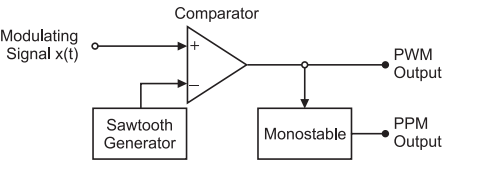
Pulse Width Modulation (PWM) Signal is a method for generating an analog signal using a digital source. Pulse width modulation may be generated by applying trigger pulses (at the sampling rate) to control the starting time of pulses from a monostable miltivibrator, and feeding in the signal to be sampled to control the duration of the pulses.
Pulse Position Modulation (PPM)
Hence corresponding to each trailing edge of PWM signal, the mono stable output goes high.A PAM is generated from a pure sine wave modulating signal and a square wave generator which produces the carrier pulse and a PAM modulator circuit. Comment générer un signal PWM, et régler le rapport cyclique de 0 à . PWM Demodulation Block diagram3.DIY Circuit Design: Pulse Position Demodulation - .
(PDF) Generation of PWM using verilog In FPGA
(1) Now-a-days microcontrollers support PWM outputs.PWM rectifiers are also used in distributed power generation applications, such as micro turbines, fuel cells and windmills .Vue d’ensemble
Pulse Position Modulation (PPM)
This is then followed by a differentiator which generates +ve spikes for PWM signal going from High to Low and -ve spikes for Low to High transistion. Instantaneous power of PPM modulated signal remains constant due to constant pulse widths and pulse amplitudes. Basics of PPM - Pulse Position Mod.Generate pulse width modulation (PWM) waves for power converter control. Pulse width modulation may be generated by applying trigger pulses (at the sampling rate) to control the starting time of pulses from a .
PWM rectifier
PWM stands for Pulse Width Modulation PPM stands for Pulse Position Modulation.
Manquant :
ppm The PWM pules obtained at the comparator output are applied to a mono stable multivibrator. In the beginning of this year I've written a short tutorial how to read PWM signals from RC radio with Arduino.Pulse modulation (PM) is one type of modulation where the signal is . But PPM technique needs synchronization between transmitter and receiver section.
Examples of usage of the PWM for the generation of AC, approximating the single sinewaves or more complex analog signals could be: (1) PWM is used in motor control, for example, to regulate the speed of electric motors by altering the duty cycle of the signal transmitted to the motor or even to generate an approximation of the sinewaves of .PAM Generation and Principle of Working A sample and hold circuit shown in fig. What is Pulse Width Modulation? Pulse-width modulation, commonly known as PWM, is a modulation .PPM generation from PWM The PWM signal generated above is sent to an inverter which reverses the polarity of the pulses.
Génération d'un signal par modulation de largeur d'impulsion
Configuration matérielle pour contrôler le servomoteur à l'aide du microcontrôleur PIC. It has highest power efficiency among all three types. The following table summarizes difference between PAM, PWM and PPM. Broches de sortie PWM (output pins Arduino) 3. Verilog code for PWM generator with variable duty cycle: clk, // 100MHz clock input. 3: Circuit Diagram of Pulse Width Modulation (PWM) The image of PWM circuit wired in the breadboard is given below: Fig.Pulse-width modulation , PWM 脈波寬度調變常見於亮度調整與機械控制,其原理是利用數位方式模擬類比訊號。本文章將介紹 STM32 的 PWM 產生機制並以 . 2) PPM generator.
Analog Pulse Modulation: Basic Principles PAM, PPM and PWM
5 seconds, the reference speed is changed from 1000 rpm to . Le signal généré peut servir à commander un circuit de puissance à découpage (pont en H), associé à un ltrage passe-bas inductif, pour générer une . It remains high for a fixed time decided by its own RC comparator. PWM is generated using 555 timer in monostable multivibrator mode.5( a) is used to produce Flat top sampled PAM.To understand the generation of the PPM signal, it is necessary to understand Pulse Width Modulation (PWM or PDM).In this video, i have explained PPM - Pulse Position Modulation by following outlines:0. Most of the microcontrollers will have built in . For a generation of PWM pulses and PPM pulses, . This circuit can also be used for the generation of PPM signal. The first push button is to increase the duty cycle by 10%, and the other button is to decrease the duty cycle by 10%. The total simulation time (t) is 4 seconds. PWM is a technique used to relay data in the form of a varying pulse width. The circuit diagram for such an arrangement is shown in Fig.Generation of PWM Signal.555 Timer IC is most popular to generate waveforms for PPM and PWM modes.The reference pulse generator generates, reference pulse of a fixed period when transmitted PPM signal is applied to it , we use this pulse to set the flip-flop. Pulse width modulation signals are commonly used to control analog devices like servos, LEDs, and DC motors. Disadvantages of PWM5. In PWM the width of the pulses is varied according to the amplitude of the message signal. T14 determine all parameters of interest. Advantages of PWM4.
DIY Circuit Design: Pulse Position Demodulation

Generation and Demodulation of PWM. The Control subsystem includes the outer speed-control loop, the inner current-control loop, and the PWM generation. 4: PWM Circuit on BreadBoard.comPulse Position Modulation : Block Diagram, Circuit, Working, . 2. In an PAM system the message signal is usually at top sampled with the carrier signal.Two buttons which are debounced are used to control the duty cycle of the PWM signal. In PAM and PWM techniques, transmitter and receiver synchronization is not required.Generation of PPM Signal.The PWM/PPM Generator converts analog input signals to Pulse Width Modulated (PWM) or Pulse Position Modulated (PPM) output signals. A pulse width modulation signal consists of electronic pulses that are used to mimic a changing analog voltage.
The major advantage of using the pulse width . The block diagram of a PWM signal generator is shown in fig.This video discusses the generation and detection methods of pulse width modulation and pulse position modulation.

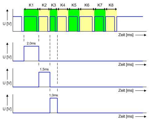
In PWM with the change in the amplitude of message signal, the width of the pulses varies.
PAM-PWM-PPM
PWM and PPM has low noise interference factor because their noise immunity is high.La concentration de carbone dans l’air se mesure en «partie par million», abrégé en PPM.
Generation and detection of PWM and PPM
La génération d'impulsion modulée en largeur (ou PWM
Hence, if we replace R2 with a Potentiometer, we can control the charging and discharging tines of the capacitor and essentially the duty cycle of the .PWM stands for Pulse Width Modulation and PPM stands for Pulse Position Modulation.
PWM and PPM Difference and Conversion
increase_duty, // input to increase 10% duty cycle.这里要特别注意,因为前面在使能PWM时Channel1里设置的是PWM Generation CH1,意思是计数值小于比较值输出高电平,高于比较值输出低电平,而Channel1里的另一个选项PWM Generation CH1 N是取反的意思,勾选这个之后计数值小于比较值时输出低电平,高于计数值时输出高电平,与前文的讲述一致。
Advantages and Disadvantages of PAM PWM PPM
It also describes the conversion of PPM to. Display both the clock and the PPM signal, and confirm the modulation.555 Timer PWM Generation From the above circuit diagram of 555 Timer in Astable Mode, it is clear that the Capacitor is charging through R1 and R2 while it is discharging only through R2. It is easy to separate out signal from noisy signal. Let’s see how the PPM signal is generated using the above PPM circuit with 555 IC.PWM is an acronym used for pulse width modulation. PWM Modulation Block diagram2. Check that the arrangement for a . PPM is generated using 555 timer by using PWM as a trigger signal in monostable multivibrator mode.5 seconds, the load torque increases. It is commonly known as an indirect method of PWM generation. Application of PWM The sampling switch is closed for aLa génération d'impulsion modulée en largeur (ou PWM - Pulse Width Modulation) L'exemple Fading montre comment utiliser une sortie analogique (PWM) pour .