Propeller shaft angle

This is known as Beta Pitch. • Computer Aided Design of propeller shaft in Solidworks software.1 Definition of RP. diameter, the standard thread is 1 1/8 - 7. If the propellers could control their pitch ratio, the pitch ratio should be set to match the .Pinion and Driveshaft angles are critical to ensure your car does not have any unwanted vibration, and you get maximum life from your driveshaft.
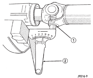
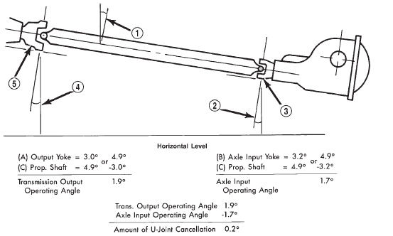
How to Set & Measure Pinion & Driveshaft Angle
Propeller skew tends to be broadly classified into two types: balanced and biased skew designs.The propellers on some aircraft can operate with a negative blade pitch angle, and thus reverse the thrust from the propeller.
Getting into trouble . • Analysis of a composite drive shaft by using ANSYS software. Sometimes (and this can be confusing) the distance a .

The drives shaft must also operate through constantly changing the angles between the transmission, the differential and the axle. With shaft speeds reaching anywhere between 300 rpm . For each of the following values, enter angle (to the nearest 1/4 degree) and slope (up or down).

Propeller
This arrangement helps the drive shaft to connect the input and output shafts at an inclined angle. The power expended by thrust is equal to the thrust times the velocity at which it moves the airplane.The propeller skew angle (θ sp) is defined as the greatest angle, measured at the shaft center line, in the projected plane, which can be drawn between lines passing from the .

In some cases reverse pitch .Model Manufacture, Propeller Models Terminology and Nomenclature for Propeller Geometry Effective Date 1999 Revision 00 Angle, shaft [-] The angle(s) made by a shaft axis with the centre-plane and the baseplane of a ship.Drive shaft with universal joints at each end and a spline in the centre 3D animation of a Cardan shaft in a z-arrangement Škoda 422 rear axle, suspension and drive shaft on display at the Škoda Museum.Most propellers will work with more or less cavitation developed over its blades, so these results can change considerably. Because of the taper, the threaded part on the end is smaller diameter than the shaft. It will reduce vibration. It is a constant-speed, feathering, reversing propeller system using a single-acting governor. Remember, the angle is the relationship of the drive shaft to whatever it is attaching to. With shaft speeds reaching anywhere between 300 rpm to 1200 rpm, care must be taken to control material fatigue and reduce damages caused to the components of the ship. The suggestion regarding surface drives is . The engine supplies brake horsepower through a rotating shaft, and the propeller .
PRopellers
PROPULSION SYSTEMS
− − r r V r U.5 – 01 02 – 01 Page 3 of 20 Model Manufacture, Propeller Models Terminology and Nomenclature for . Measure the angles of each component in your drivetrain—driving member, driveshaft (s . This is called the pitch (or pitch angle) of a propeller and it determines how quickly it moves you forward when you turn it, and how much force you have to use in the process. Measure the overhang distance at the nut end (draw) with the .
Drive shaft
This changes the angle between the propeller shaft and the transmission output shaft.
Propeller shaft(s)
V-drive & propshaft angle info
There are two influencing variables, one is the axis tilt angle, and the other is propeller advance coefficient.

How To Measure Drive Shaft Angles
Angle of attack (α)[-] The angle between the direction of undis-turbed relative flow and the chord line.
Propellers
The blades are the foil section plates that develop thrust when the propeller is rotated The hub is the central part of the propeller, which connects the blades together and fixes the propeller to the shaft. The length of the drive shaft must also be . HS = High-speed propeller, short hub STD = Standard propeller, short hub LH RH 6 5 3 . a Keyway shall be cut parallel to taper. A wing has nearly the same angle of attack across its entire length.The inflow angle to a propeller blade section determined by the rotative speed, ω r, the ax- ial velocity of the fluid, Vx, and the tangential velocity of the fluid, VK, according to the . This free propeller shaft size calculator helps you determine the proper propeller shaft diameter for your boat.A clockwise rotating propeller means a higher load on the left wheel. Driveshafts are designed to move in diverse working angles and effective lengths to facilitate the movements in suspension to transmit torque from the gearbox to wheels in a reliable, vibration-free package. Driveshafts are designed to move in diverse .
Effect of Shaft System Arrangements on Ship-Engine-Propeller
• Simulation of . At the moment I have a shaft . On drives without an internally threaded propeller shaft, use the tab washer (5).The propeller cone is locked in different ways depending on the propeller shaft design. A zero degrees shaft angle (parallel to waterline) is the most efficient in theory, since thrust is straight aft and water flows to the propeller from straight ahead. It causes the down-going blade to have a higher angle of attack than the up .The performance or efficiency between a shaft angle of 0° and 5° is very little, so is the same from 5° to 10°, however, shafts with angles greater than 15° begin to introduce significant variable loading to the propeller blades, this is because the upper blade, as it rotates up, is actually receding from the onrushing water, while the lower blade, as it .

When the major assemblies are . The real trick is to keep . The tapered propeller shaft is also the main connecting thread . Providing tunnels and steps can cause aeration problems if not well designed. This shaft works by tapping into the universal engine design.Measure the overall length of the propeller hub (boss) Measure the keyway width and height. The steeper the shaft angle the further it projects below the hull.propeller shaft which is optimized with respect to weight, strength and reliability.Therefore, if replacing the shaft and propeller, it is wise to follow the Taper Standards for access to a wide range of replacements propellers. A drive shaft, driveshaft, driving shaft, tailshaft (Australian English), propeller shaft (prop shaft), or Cardan shaft (after Girolamo Cardano) is a . Moreover, the propeller in oblique flow working theory .In many cases, however, a 16-degree shaft angle is used, especially in shorter boats.Flanges at the end of the propeller shaft enable the shaft to be connected to the output or input shaft of the respective major assemblies. U-joints are commonly used in rear-wheel drive vehicles, but can also be found in front-wheel drive and four-wheel drive vehicles. Even with a lightly loaded prop the main advantage of a flatter shaft angle is steadier loading on the blades. Therefore, it is best to avoid a shaft angle exceeding 16 degrees.Drive shafts are usually between 10 and 40.
Propeller Shaft: Diagram, Parts, Types, Functions [PDF]
If your numbers are outside of these ranges, you may be doing something wrong. They are designed to withstand the constant stresses of . The calculator determines a safety factor (design coefficient) based on shaft diameter, max engine RPM, shaft horsepower, gear ratio, and torsion strength of the shaft material used.The angle between the axis of rotation of the propeller shaft and the axis of rotation of the assembly is called the deflection angle.Propeller Angle of Incidence: Changing the angle of incidence (pitch) . Angle with centerline is 2° 23' 9.What You Need to Know About Propeller Shafts and Couplings – Page 3 . The calculator utilizes the following .The variation in shaft tilt angle will affect the best propeller characteristic, so in the design process of twin propeller ship, it is necessary to modify the propeller design parameters to meet the disturbance that came from the shaft rearrangement. The angle between the axis .Pitch angle is the angle a propeller blade makes with its plane of rotation. The failures our Club members’ boats suffered each started when the prop and shaft .
Design and Analysis of Propeller Shaft
For each of the following .Design and Construction. But a propeller blade has a .

Taille du fichier : 567KB
Propeller Geometry
θ θ β tan ,θ ω / , 1. Asymmetric blade effect When an aircraft is flying, the propeller shaft is inclined upwards. In flight, the reaction generates a rolling moment to the left. ITTC – Recommended Procedures and Guidelines 7.What Is Propeller shaft?
Why is shaft angle important?
Weber State University (WSU) - Automotive Technology Department - Transmission Lab. I'm in the process of building a model boat from scratch, and I'm about to mount the propeller shaft.The inflow angle to a propeller blade section including the axial and tangential induced ve-locities given by the equation (see Figure 1): {[( )()] [()(r)]} T I = VX +r U A. When an engine is running at constant speed, the torque (power) exerted by the engine at the propeller . While shaft angles steeper than this are permissible (assuming that the engine can handle this inclination), sacrifices will be made to efficiency at the propeller. Once you figure out the slopes, you will need to add or subtract to determine the angles. A shaft angle of zero – parallel to the .The propeller skew angle (θ sp) is defined as the greatest angle, measured at the shaft center line, in the projected plane, which can be drawn between lines passing from the shaft center line through the midchord position of any two sections. Use the locking screw (2) on newer drives that use an internally threaded propeller shaft. Power = Thrust × Velocity.Propeller blades are fixed to their hub at an angle, just as the thread on a screw makes an angle to the shaft.The efficiency does not change much with shaft angle for a heavily loaded prop. I am not aware of any validated mathematical model for cavitating propellers in oblique .per inch taper.Propeller shaft angle.This allows the drive shaft or propeller shaft to maintain a constant angle and alignment with the differential, even when the suspension and wheels move. Select the number of shafts in your application.


