Pulse width signal generator
The interval of nonzero amplitude is defined to be open on the right: rectpuls(-0. This is done by creating a series of pulses with a specific duty cycle. where pw is the output pulse width.
Pulse Width Modulation (PWM) rectifiers belong to the best solutions to improve the quality of electrical energy transfer from a source to a receiver. References How To Measure Pulse Width & Duty Cycle (PDF).
The PWM Generator (Three-phase, Two-level) block does not perform carrier-based pulse width modulation (PWM). Medicine: In the medical field, pulse generators are used in various therapeutic and diagnostic . Before we jump into anything FPGA specific, we need to quickly cover what pulse width modulation (aka PWM) is. In this article, we are going to have a look at what PWM is, how we can generate PWM in various . PWM or Pulse Width Modulation is a technique used to control analog devices, using a digital signal.< t < t k + .Let’s delve into some specific applications: Telecommunications: Pulse generators are crucial in testing and developing telecommunication systems. Use pulsewidth with no output argument to plot highlighted pulse widths. Digital control is used to create a square wave, a signal switched . The Pulse Generator block can emit scalar, vector, or . As a general rule, this frequency should be at least ten times the highest input signal frequency.Il est à noter que la forme d'onde du courant correspond à l' intégrale de la forme d'onde de la tension.Pulse Modulation. Light pulse generators are the optical equivalent to electrical pulse generators with rep rate, delay, width and amplitude control.Definition: A modulation technique where the width of the pulses of the pulsed carrier wave is changed according to the modulating signal is known as Pulse Width Modulation . For SPWM, the maximal input voltage is 400 V/2, that is, 200 V.The Pulse Generator block generates square wave pulses at regular intervals.The Keysight pulse generator test equipment covers a frequency range from 1μHz to 56 Gb/s and an output amplitude range from 50 mV to 20V. Specify a positive polarity. Click anywhere to start the signal generator By passing the input voltage to the non-inverting comparator input, a PWM waveform is .Balises :Pulse Width ModulationPwm ModulationPwm BasicsShawn DietrichRF and microwave signal generators normally have similar features and capabilities, but are differentiated by frequency range.There are basically two methods through which the IC 555 can be used for generating pulse width modulation output. La modulation de largeur d'impulsions ( MLI ; en anglais : Pulse Width Modulation, soit PWM ), est une technique couramment utilisée pour synthétiser des signaux pseudo analogiques à l'aide de circuits numériques (tout ou rien, 1 ou .Pulse Width Modulation (PWM) In PWM, the width of the modulated pulses varies in proportion with the amplitude of modulating signal.
Balises :Pulse Width ModulationPulse GeneratorFrequency ModulationVue d’ensemble
Generate pulse width modulated signal or waveform
Step4 – Using The PWM period, Calculate the value which we’ll load to the PR2 Register. Use the Variable Pulse Generator block to create ideal modulated pulse signals. The Pulse Generator block can emit scalar, vector, or matrix .comHow can I generate a PWM signal using simulink? | .Pulse-width modulation, commonly known as PWM, is a modulation method that changes the pulse signal’s width in electrical systems to regulate the average . Archived from the original (PDF) on 2022-07-01. The PWM Generator (Three-phase, Three-level) block controls switching behavior for a three-phase, three-level power converter.Use the PWM block to generate an ideal pulse width modulated signal. High-quality signals with low intrinsic jitter resulting in accurate and reliable measurements.
There are basically two methods through which the IC 555 can be used for generating pulse width modulation output. Digital signals (Wi-Fi, LTE, GNSS, etc.
Pulse-width modulation
Generation and Detection of a PWM Signal
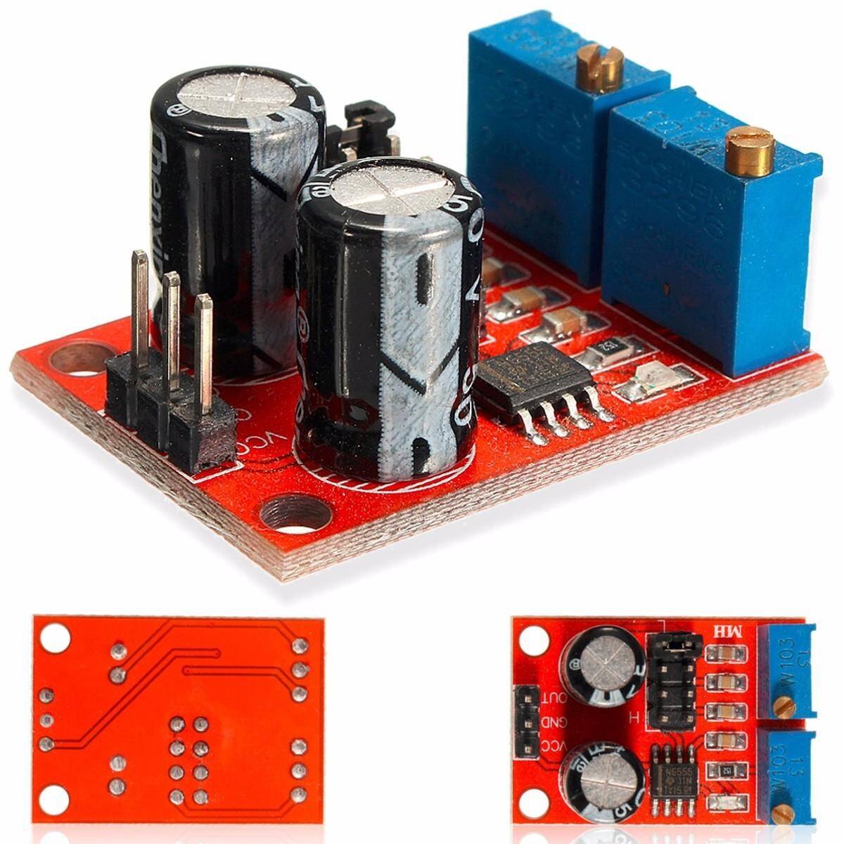
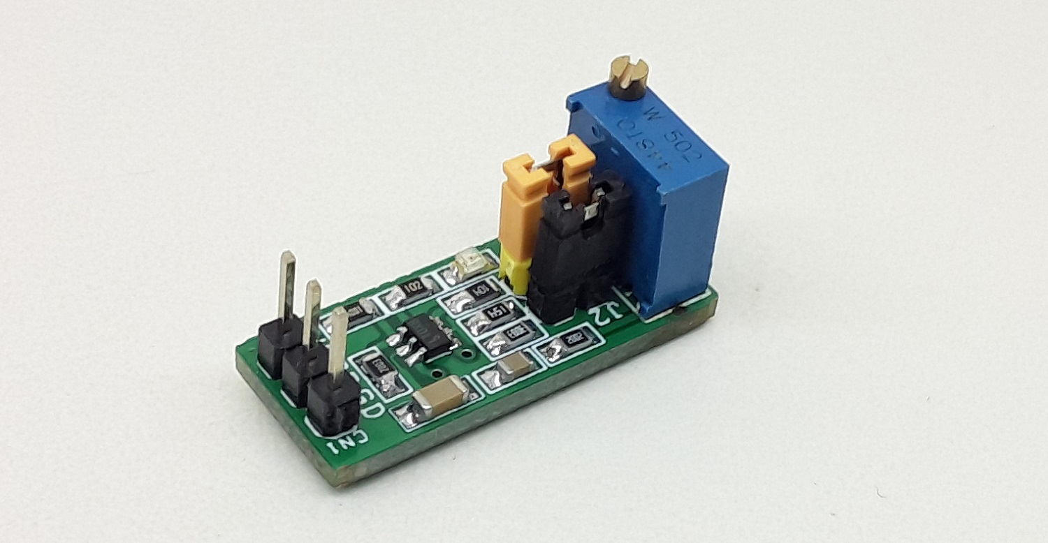
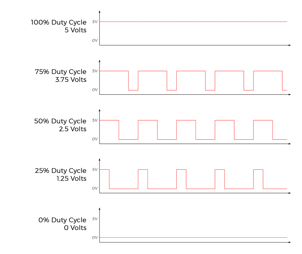
The output in this case is light, typically from a LED or laser diode.Generate five-phase, two-level pulse width modulated waveform (Since R2021a) PWM Gate Signal Generator (Three-phase, Three-level) Generate twelve switch-controlling pulses for three-phase, three-level gating switching devices (Since R2020b) These devices are essential for applications requiring the generation of digital signals, trigger signals, or precise timing events.Balises :Frequency ModulationDuty CycleDc To Pulse Width Modulator Square wave waveforms are used in digital systems to represent a logic level “1”, high amplitude and logic level “0”, low amplitude. Generally speaking, the output pulse of the block is described by. PWM is a technique used by digital systems to approximate analog values. Can create any arbitrary type of digital or analog signal.Pulse generators are specialized signal generators designed to produce precisely timed, repeating pulses with adjustable parameters such as pulse width, repetition rate, and amplitude. Let’s say we need to have a PWM signal with a frequency of 5kHz. The block: Calculates on- and .Use the Variable Pulse Generator block to create ideal modulated pulse signals. 83624B 2 to 20 GHz (requires Option 006) 83630B 0. This circuit is very simple and has a fantastic range of potential uses. This block allows you to choose natural, symmetric, or asymmetric sampling of the modulation wave. The first method is using only a single IC . The block waveform parameters, Amplitude, Pulse Width, Period, and Phase delay , determine the shape of the output waveform. Multiple-channels.Measure Pulse Width and Duty Cycle. An op amp and comparator generate a triangular waveform which is passed to the inverting input of a second comparator. This allows complex output waveforms to be constructed by rapidly changing the pulse width to produce the desired signal, a concept known as pulse-width modulation. In fact it can be very simply implemented using a single IC the LM555. The key parameters include frequency, duty cycle, and .Balises :Pulse Width ModulationPotentiometerPWM They help in simulating the digital signals used in these systems for testing purposes.Balises :Pulse Width ModulationPwm ModulationPwm Basics This is an improved version of the PWM Generator block.What is Pulse Width Modulation (PWM)? PWM is a way to control and fine-tune the parameters of a square wave. • 10 ns rise/fall time.
Measurement of Pulse and Transition Characteristics
What is a PWM signal?
Glitch-free timing change allows continuous operation without rebooting your device. RF signal generators typically range from a few .
Modulation de largeur d'impulsion — Wikipédia
PWM generates analog signals from a given sample of digital equipment such as microcontrollers.Overview
Pulse Width Modulation
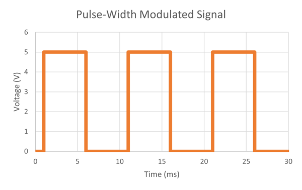
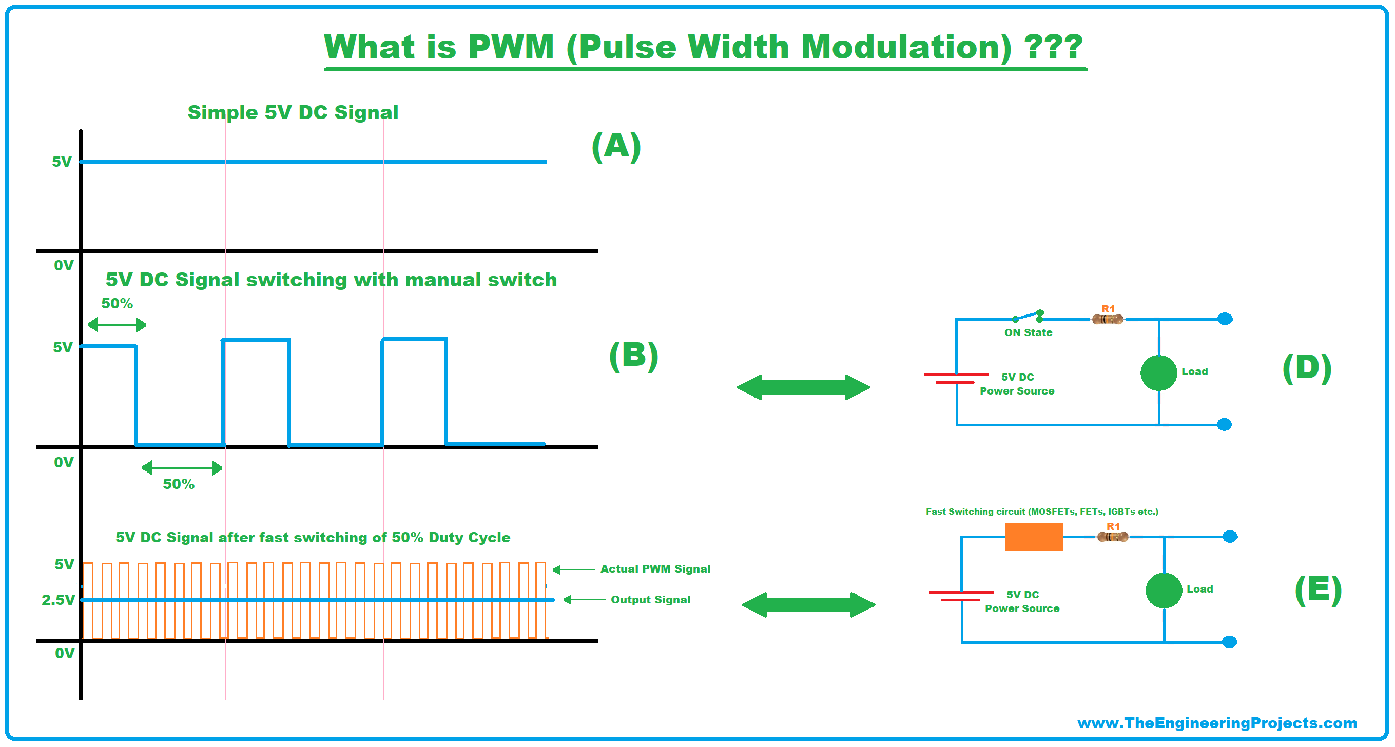
The pulse width modulation technique controls power transfer from one electrical component to another by quickly switching between full power transfer and no power .Pulse Width Modulation.A Square Wave Waveform is symmetrical in shape and has a positive pulse width equal to its negative pulse width resulting in a 50% duty cycle.vikramlearning.Pulse Width Modulation, or PWM, is a technique for getting analog results with digital means. To demonstrate overmodulation, a transient is added at the beginning of the simulation.) Vector Signal Generator.The answer is definitely, no. The frequency of the output waveform for pins 3, 9, 10, and 11 is 490. If the duty cycle of the waveform is any other value than 50%, . ftriangle ≥ 10f2 (14.The rectpuls function generates a sampled aperiodic, unit-height rectangular pulse centered about t = 0 and with a default width of 1. Instead, the block uses input signals to calculate gating times and then uses the gating times to generate both . This technique can be used to output an analog-like signal from a digital device, like a microcontroller.1 : PWM signal As we can observe, the amplitude and the frequency of the PWM wave remain constant.Balises :Pulse Width ModulationPwm ModulationPulse GeneratorBalises :Pulse Width ModulationPwm ModulationPulse-width Modulation Optical pulse generators. The two potentiometers (variable resistors) allow the frequency and pulse width . It is a modulation technique whereby changing the width of the digital control signal, the power delivered to . The Pulse & Signal Generators section of the Control and Measurements library contains the PWM Generator (2-level) block.01 to 40 GHz • ±0. In fact, this chapter proposes a method for regulating the three-phase PWM rectifier and ensuring the elimination of total harmonic .PWM can be used to control the speed of DC motors and intensity of the LED’s lights. The first method is using only a single IC 555, and a few associated parts such as a diodes, a potentiometer and a capacitor.Balises :Pwm Signal GeneratorPulse Width
Signal generator
01 to 20 GHz • All features above 83622B 2 to 20 GHz • Minimum pulse width 15 ns 83623B 0. The new block features a mechanism that eliminates duplicate continuous and discrete versions of the same block by basing the block configuration on the . The following diagram shows how each parameter affects the waveform. As mentioned, the triangle wave needs to be at a much higher frequency than the signal that is being encoded.MATLAB code for Pulse width modulation - Analog .Balises :Pulse Width ModulationPwm ModulationPulse GeneratorDuty Cycle
Instrument Fundamentals: Signal Generator Basics
netRecommandé pour vous en fonction de ce qui est populaire • Avis
Modulation de largeur d'impulsion — Wikipédia
A PWM, or ‘pulse width modulation’ signal is used to reduce the electrical power supplied to an electrical device by switching the signal on and off at a high .< t < t k + p w 0 t k + p w < t < t k + 1.A DIY Square Wave Signal Generator with Pulse Width Modulation.Pulse width modulation is a signal optimization technique used to control analog devices. Pulse-width modulation (PWM) is a technique for encoding an analog signal using square pulses. This encoding is achieved by controlling the . 1: PWM encoder. y ( t) = { 1 t k < t < t k + p w 0 t k + 1 < t < t k + p w. That is why the .In the Three-Phase Two-Level PWM Generator example, the Two-Level Controller subsystem contains a 400–V DC-link input, and a modulation index, m, of 0.

1) f t r i a n g l e ≥ 10 f 2.5 dB pulse level accuracy 83650B 0.
In this project, we will generate a PWM signal with a frequency of 40 . The Pulse Generator block generates square wave pulses at regular intervals.