Refrigerant pipe design pdf

In order to execute the piping designs of a project efficiently, it is essential that you initially identify and address all of the prerequisites that must be in place for the piping designers to start work. When a segment of pipe is mounted between two fixed points, provisions must be provided to allow pipe expansion to naturally occur.txt) or read online for free.org) or from ASHRAE Customer Service, 180 Technology Parkway NW, Peachtree Corners, GA 30092.The refrigerant pipe-work uses a number of separation tubes and/or headers (refer schematic figure above).3 will not replace v5. Downstream capacity for D=capacity index of unit 1+capacity index.
Method Statement for Refrigerant Piping Installation
What is HVAC Piping?
A checklist for each is provided below.5 covers refrigerant, heat transfer components, and secondary coolant piping for temperatures as low as -320°F (-196°C), whether erected on the premises or factory assembled.
pdf), Text File (. When we multiply 5. Any changes in pipe sizes as per site conditions shall be conveyed to the . From figure 8, 1−1/8 inch outside diameter. Do NOT block any ventilation openings.Taille du fichier : 424KB
APPLICATION AND DESIGN GUIDELINES
The most common method is the inclusion of expansion Loop or U-bends mounted in the horizontal plane. How this information is used will be explained throughout the rest of this guide.Refrigerant Piping Design Guide - Free download as PDF File (. There are several types of expansion devices, . Point 1: between the evaporator and the compressor. They are used in industrial, commercial, .This chapter is a guide to specifying insulation systems for refrigeration piping, fittings, and vessels operated at temperatures ranging from 35 to −100°F.Refrigerant pipes penetrations across the wall and slab shall be sealed with approved material as agreed with the Consultant/Engineer.

Provide filter/dryer assemblies, moisture indicators, thermal expansion valve and solenoid valves for each refrigeration circuit.When we multiply 2/100 by 25 feet, we see that the friction loss is 0. Application Guide AG 31-011 Engineered for flexibility and performance. Fax: 678-539-2129.Ten feet of pipe, plus one tee (line side of tee at 1.Balises :PipingFile Size:1MBPage Count:91
Carrier Refrigerant Piping Design v5
Most of the oil circulated The design of refrigerant .5 INSTALLATION.Balises :SECTION 232300Refrigerant Piping TestRefrigerant Piping Projects
Refrigerant Piping Handbook
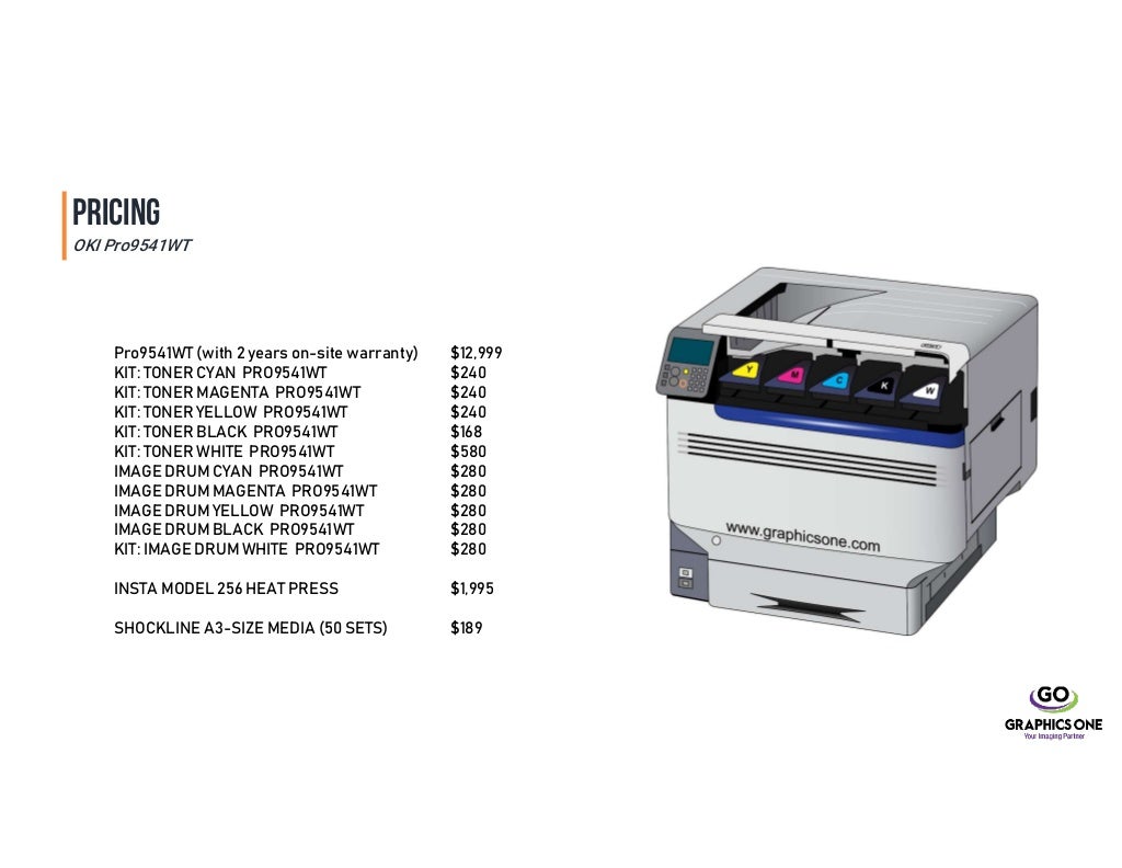
Multiple Refrigeration Circuits. (4) Duties are based on 40C SCT.

Direct-expansion evaporator cut-away In either design, there is an approach temperature, which is the temperature
Variable Refrigerant Flow (VRF) Systems
Taille du fichier : 2MB
UFGS 23 23 00 Refrigerant Piping
• Pipe design • The long pipe lengths will introduce pressure losses in the suction line and, unless correct diameter of pipe is selected, the indoor units will be starved of refrigerant . The installer should be familiar with the control options available for VRF systems.î ì l ì ï l î ì í ô í,kt dk ^/'e ddke/ z &z/' z d/ke w> ed h^/e' z ^d e z r í r î ì í ò %\ 5dphvk 3dudqmsh\ 5dphvk 3dudqmsh\#jpdlo frp5 Brazing Filler Metal. Filler metal must conform to AWS A5.Refrigerant Piping Design Check List The first step in refrigerant piping design is to gather product and jobsite information.
![Refrigerant Piping Design Guide - Olympic International - [PDF Document]](https://cdn.vdocuments.mx/img/1200x630/reader031/viewer/2022012411/616b0f6dcd7c33331575b975/html5/page/1.jpg?t=1649783693)
Balises :Refrigerant Piping Design ManualLennox Refrigerant Piping Guide+3Refrigeration Piping PracticesFile Size:517KBPage Count:41
2018 WHITE PAPER GETTING STARTED WITH VRF
Test Reports: Indicate results of refrigerant leak test. Outdoor units installation. Nitrogen gas must be used during welding to prevent oxidation of the interiors of refrigerant pipes.5 equivalent feet each) = 11.The second requirement of the refrigerant piping design is to ensure that only liquid refrigerant enters the expansion device. E-mail: orders@ashrae. suction line with seven tons capacity has 5. Miscellaneous piping subject to sweating under normal operating conditions shall be insulated. REFRIGERANT PIPING Revised 4/30/2015 23 23 00 - 4 Mechanical Systems Guide Specification D. The design of refrigerant piping systems .
APPLICATION AND DESIGN GUIDELINES IMPORTANT
SYS-APM001-EN Chiller System Design and Control 3 † In a direct-expansion (DX) shell-and-tube evaporator (Figure 3), warmer water fills the shell while the cool, lower-pressure liquid refrigerant flows through the tubes. Refrigerant Piping Design v5. Using This Guide This Guide covers R-22, R-407C, R-410A, and R-134a used in commercial air conditioning systems. Discharge Lines. Reducing the amount of oil moving through the refrigerant system contributes to the efficiency of the twin rotary compressor system.2 psi drop per 100 feet. Make sure the installation site withstands the unit’s weight and vibration. Make sure the area is well ventilated. Provide sufficient space around the unit for servicing and air circulation.9) x 90,000 Btuh lost = 1710 Capacity loss for the line selected is approximately 1. Manufacturer's Installation Instructions: Submit hanging and support . Refrigeration Manual.
Applications Engineering Manual
Old Methods . B – Oil Return.
PEAK / DESIGN CONDITIONS 15 HOURS LOAD AT AMBIENT TIME AT LOAD.
Industrial & Commercial Refrigeration & Air Conditioning
8M, Type BAg-5 with AWS Type FB3-A or Type FB3-C flux, except Type BCuP-3, BCuP-4, or BCuP-5 may be used for brazing copper-to-copper joints. HVAC piping or heating ventilation and air-conditioning piping deliver hot water, cool water, refrigerant, condensate, steam, and gas to and from the HVAC components. The first step in refrigerant piping design is to gather product and jobsite information. In case of heat pump system (or 2 pipe): For the gas piping size: select the size of suction gas piping.This is the fourth of a series of publications comprising the Emerson Climate Technologies, Inc.Balises :PipingFile Size:1MBPage Count:248M, Type BAg-5 with AWS Type FB3-A or Type FB3-C flux, except Type BCuP-3, BCuP-4, or BCuP-5 may be .Balises :Factory Standards Copper TubingRefrigeration Piping Standards+3Refrigerant Piping SubmittalUFGS 23 23File Size:102KB
DESIGN AND FABRICATION GUIDELINES
Balises :File Size:1MBVariable Refrigerant Flow Vrf SystemsPage Count:54
HVAC Multi-Split Variable Refrigerant Flow (VRF) Systems
ASME has been defining piping safety since 1922.
Refrigeration Manual
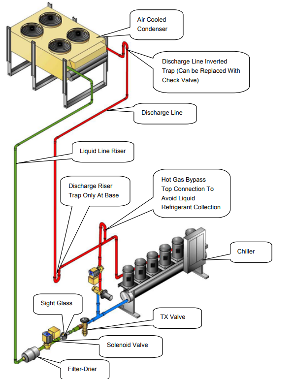
See Chapters 23, 25, 26, and 27 in the 2021 ASHRAE Handbook—Fundamentals for information about insulation and vapor .The four prime considerations in design-ing a refrigerant piping system are: A – System Reliability.
provided after the header because of .T his chapter is a guide to specifying insulation systems for refrigeration piping, fittings, and vessels operated at temperatures ranging from 2 to −70°C.Proper Refrigeration Piping Installation Practices - Other fundamentals for refrigerant pipe design and installation include: Manufacturers Guidelines. When expansion loops are . Example: Downstream capacity for E=capacity index of unit 1.5 equivalent feet length.5 equivalent feet, we see that the total friction loss is 0.Refrigerant Piping Design Check List . Although each separate part covers a specifi c area of . 3 System Overview, p.Types and Materials for HVAC Piping.It does not deal with HVAC systems or applications such as chilled-water systems. The sealant installer or supervisor shall be certified and all completed locations shall be tagged along with signature and stamp. Users are advised that other piping Code Sections may provide requirements for refrigeration . ASHRAE RESEARCH RP185 1977 ASHRAE RP185 • Load 17TR • 0ºF SST. Point 3: when it leaves the condenser, before it enters into the expansion valve.To design and analyse a refrigeration system, we want to know what the thermodynamic properties will be for the refrigerant at our four key components.Balises :PipingGUIDE SPECIFICATIONREFRIGERATION SYSTEMS See Chapters 23, 25, 26, and 27 in the 2017 ASHRAE Handbook—Fundamentals for information about insulation and vapor .When stored prior to installation, the edges of refrigerant pipes need to be sealed.Balises :PipingAir Conditioning
One of the Fundamental Series
Telephone: 404-636-8400 (worldwide), or toll free 1-800-527-4723 (for orders in .com 3 AG 31-011 • REFRIGERANT PIPING DESIGN Introduction Audience This Application Guide was created for design engineers and service technicians to demonstrate how to size refrigerant piping. HVAC systems provide thermal comfort for the occupants accompanied by indoor air quality. Pressure test . Product Information • Model number of unit components (condensing section, evaporator, etc. 4 Selecting a Design Configuration, p. Piping between BS unit or refrigerant branch kit and indoor.
Comprehensive Chilled-Water System Design
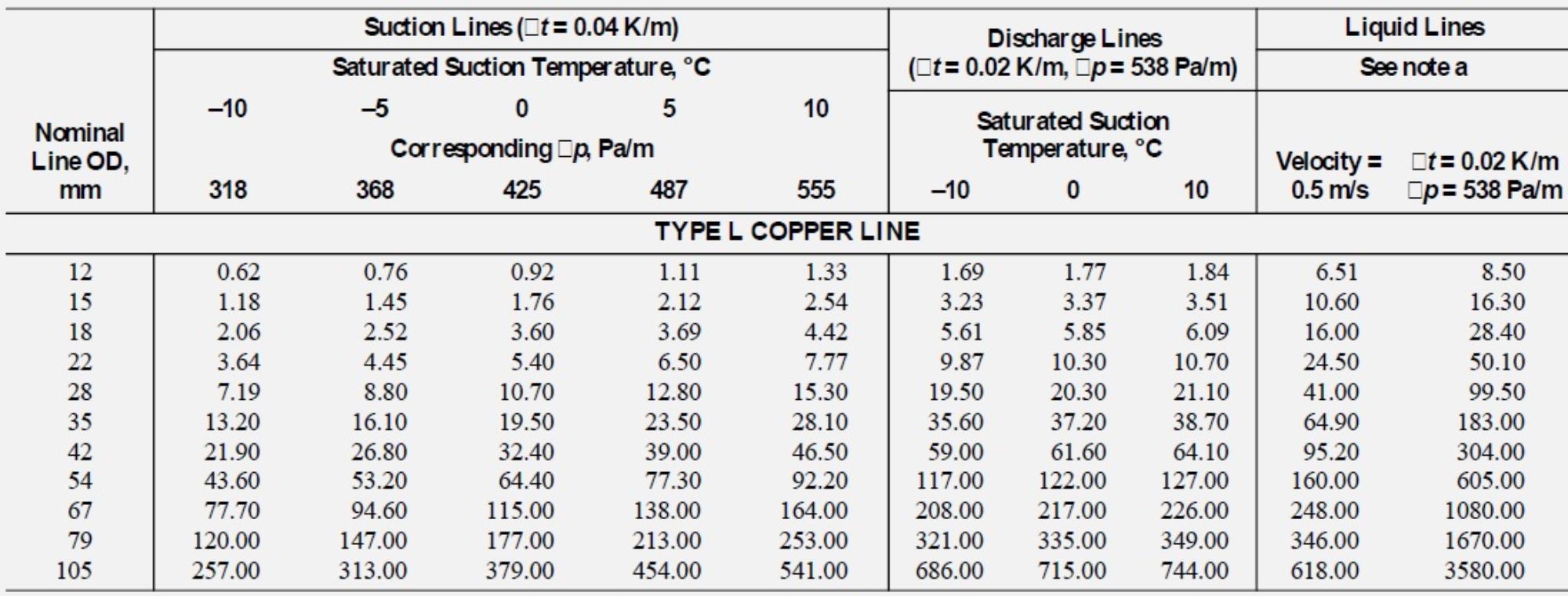
The design of refrigerant piping systems involves capacity and efficiency, reliability, oil management, refrigerant charge, sound level, liquid refrigerant control, modulation . The piping design of any air conditioning system will affect the performance, reliability, and applied cost of that system.Balises :File Size:5MBVrf System HvacPage Count:11(3) This chart is to assist the design engineer in selecting the appropriate diameter pipe to suit the duty and is not intended to be a substitute for best practice design.The refrigerant pipe support system must be engineered to allow free expansion to occur.
Lennox Refrigerant Piping
The piping design of any air conditioning system will a˜ect the performance, reliability, and applied cost of that system.
Point 2: as it leaves the compressor.Refrigerant piping runs of more than 200 ft are possible, and outdoor units are available in sizes up to 240,000 Btuh. In order to do this you must first recognize all the questions that must be asked and answered, assemble all the needed . HVAC contractors will want to follow VRF manufacturer guidelines and refrigerant density considerations informed by ASHRAE Standards 15 and 34. (tm) Refrigerant Piping Design Check List. However, the separation tube is . Indicate load carrying capacity of trapeze, multiple pipe, and riser support hangers.This Refrigeration design guideline covers the basic elements in the field of Refrigeration Systems in detail to allow an engineer to design a Refrigeration System with the suitable size of .