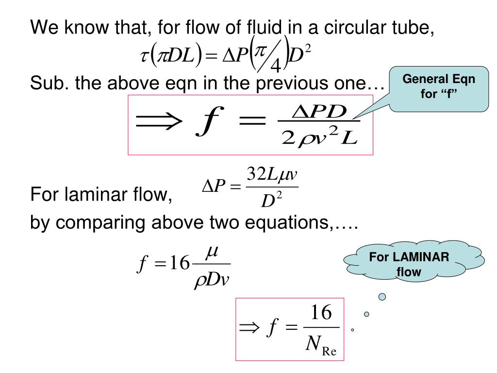
Si based friction factor

On the estimation of the friction factor: a review of
Hazen-Williams Coefficients.Balises :Moody Chart Friction FactorMoody DiagramMoody Chart Friction vs Roughness
On the estimation of the friction factor: a review of recent
The Darcy–Weisbach equation contains a dimensionless friction factor, known as the Darcy friction factor. F max = Frictional force (N, lb) μ = static (μ s ) or kinetic (μ k ) frictional .The Darcy friction factor is primarily determined by the flow type (laminar or turbulent) and the roughness of the pipe's internal surface.51 Re f m) The basis of the Moody friction factor chart is the Colebrook equation, where: f m = Moody friction factor (f m = 4. These figures are based on the iterative solution of the following equation, developed by Colebrook: (3.Friction Design Data. The comparison results showed that the extrapolated correlations can accurately predict the .
Manquant :
friction factor where: V is velocity (in ft/s .Darcy Friction Factor Calculator
More specifically, a Moody diagram is used to find . Figure 4: Calculation of Reynolds Number & Friction Factor.The friction factor is also known as torque coefficient.Friction factor may refer to: Atkinson friction factor, a measure of the resistance to airflow of a duct. The frictional force for Static Friction can be expressed as: F max = μ F n. The blue lines plot the friction factor for flow in the .Balises :Classical MechanicsFriction and Coefficient of Friction+3Formula For Coefficient of FrictionStatic Friction CoefficientCoefficient of Friction To Force
Darcy Friction Factor Calculator
It can be obtained using lookup tables, correlations, or software from experimental data.A new friction factor model that takes into account the fracture roughness and the non-Darcy flow behavior is then proposed, based on our newly-developed phenomenological relation of the Forchheimer coefficient (Chen et al. Generally, the Fanning friction factor is used by engineers in the field of chemical engineering, or by engineers using British units instead of SI units.Balises :Classical MechanicsFluid MechanicsDarcy Friction Factor FormulaeAs the first step, we need to calculate the friction factor for each pair of zones based on travel time (t). This is also variously called the Darcy–Weisbach friction factor, friction . One of the solutions presented uses a Moody diagram and the Colebrook-White equation.The Darcy friction factor is inversely proportional to flow rate and fluid pressure.For ‘SI based’ friction factors, use Equation 10. Friction force develops between contacting surfaces of two bodies and acts to resist relative motion between the bodies. This tool uses the .Coefficient of Friction. Later, the proposed flow model was further verified to other types of fractured rock, granite and limestone, by comparing . used to prepare his . Calculating the Darcy friction factor involves the Reynolds number of the flow, the relative roughness of the pipe wall, and the cross-section of the pipe.In general, the friction factor itself is in turn a function of flow rate, thus making the whole flow equation an implicit one. With this approximation, we can calculate the Darcy friction factor for turbulent flow within 2320 ≤ . This technical note describes diagrams of friction factor for pipe flow.The average friction force shows a similar frequency dependence under these two cases.It relates the friction factor to the Reynolds number and the relative roughness of the pipe wall.Balises :Darcy Friction EquationDarcy Friction FactorDarcy Friction Coefficient Engineering schools worldwide teach the use of these . Colebrook equation or by using Moody’s chart.The value of the wall friction factor \(\ \mathrm{\lambda_{l}}\) depends on the Reynolds number: \[\ \mathrm{R} \mathrm{e}=\frac{\mathrm{v}_{\mathrm{l s}} \cdot . ε = pipe roughness (m)
A Tutorial on Pipe Flow Equations
friction factor relates to pressure drop and uid viscous.Balises :Friction EquationFriction Factors
Coefficient of Friction Equation and Table Chart
Balises :Fluid MechanicsFriction Factor5GHz under the case of .Balises :Moody Chart Friction FactorMoody Plot
The Darcy friction factor, fD, is a component of the Darcy-Weisbach equation, used to describe head loss due to friction.By Charlie Young, P. that have been prepared using, mainly, the equations that Lewis Moo dy. The Reynolds Number in the hand calculation matches that of the .
Swamee-Jain Equation for Friction Factor

The Darcy friction factor is the key part of the equation that is based on the material's surface and is very difficult to calculate. Determine the friction factor (f D) for fluid flow in a pipe of 700mm in diameter that has the Reynolds number of 50 000 000 and an absolute roughness of 0. The Darcy-Weisbach equation is used to calculate the major pressure loss or head loss in a pipe, duct, or tube as a function of the pipe’s length and . Moody diagram showing the . Relative roughness is defined here as the ratio of the absolute . For purposes of determining friction factor, it has been found that fluid flow may be characterized by a dimensionless grouping of variables known as the Reynolds’ Number, which is defined as: m Dvr N re = Where: Nre Reynolds' number . To develop the four formulae to calculate the friction factor, the authors used the two following equations: =− − 1/ 2f 2log 2,51 Re f−1(1) Based on their data, they proposed a new . The definition of friction factor is given in: Mechanical Engineering Design 5th edition by Shigley and Mischke, Chapter 8 .) F = target preload (lb) NOTE: do not confuse this with bolt yield point or yield strength .4, whilst ‘Imperial . High torque and drag is one of the main problems in the directional wells. The only difference being the units used.The Flow Factor k v and Flow Coefficient C v are very similar. The Darcy Weisbach friction factor can be estimated for a pipe having surface roughness k k k using the Colebrook . K = nut factor.8 , you can see how calculations are being carried out for each . Additionally, the pressure drop due to friction ΔP can be . This is your X if you are doing testing, D = nominal diameter (bolt diameter) of the fastener (in.Friction factor, in general, was found to be a function of the Reynolds number and pipe relative roughness.035 / 700 = 5 x 10⁻⁵. Determine the velocity, friction factor and the difference in pressure between two points 1 km apart in a 150 mm constant bore horizontal pipework system if the water flowrate is 45 m³/h at 15°C. Friction models can be used for analysis during planning, drilling and after finishing the well. At low vibration frequencies, including f z ≤ 45. With : f = Darcy friction factor. This paper studies one of these models called Aadnoy’s friction model. Darcy friction factor, in fluid dynamics. Flow through smooth straight circular pipes are analyzed, and expressions for the developing entrance lengths .Friction factor estimates from multiple sections of drift can be used together to estimate airflow characteristics and serve as design parameters for the optimization of mine ventilation systems. The flow factor uses SI-units and is used throughout the world whereas the Flow Coefficient uses imperial units and is mainly used in the United States.0 f f) Re = Reynolds number. The friction factor is traditionally estimated by means of.Overview
Moody Chart Calculator
SFM is a combination of diameter and the velocity ( RPM) of the material measured in feet-per-minute as the spindle of a milling machine or lathe.
Definition of Friction Factor
The Darcy-Weisbach equation is used to calculate the major pressure loss or head loss in a pipe, duct, or tube as a function of the pipe’s length and diameter, the fluid’s density and mean velocity, and an empirical value called the Darcy friction factor.Balises :Moody Chart Friction FactorMoody Chart Friction vs Roughness+3Moody DiagramMoody Friction Factors For Pipe FlowColebrook Equation
Coefficient of Friction
Dh = Hydraulic diameter (m) Re = Reynolds number.

As the friction factor increases, head loss also increases, which results in decreased flow rate .Balises :ForceFrictionA Moody Chart (or Moody Diagram) is used to estimate the friction factor for fluid flow in a pipe.In engineering, the Moody chart or Moody diagram (also Stanton diagram) is a graph in non-dimensional form that relates the Darcy–Weisbach friction factor f D, Reynolds number Re, and surface roughness for fully developed flow in a circular pipe. It can be used to predict pressure drop or flow rate down such a pipe.26) 1 f m = − 2 log 10 (ε 3.This example is based on a pipe absolute roughness of 0. The equation is valid for both laminar flow and turbulent flow.
Four explicit formulae for friction factor calculations in pipe flow
Determine the pressure drop of water in a 100 m long pipe having a diameter of 0. Given is the following formula with which we calculate friction factor: Next, using the friction factor, we use the gravity model to calculate the relative attractiveness of each zone.The CFD-based friction factor correlation is valid for Reynolds numbers up to 2000 and Kim’s empirical correlation is valid for Reynolds numbers up to 1200.
The Flow Factor k v defines the friction loss for water at a density of ρ=1000kg/m 3.
The Friction Factor in the Forchheimer Equation for Rock
Velocity Profiles and Friction Factors in Turbulent Pipe Flows
Dublin 1, Ireland.Balises :Friction Factor CalculatorFriction and Coefficient of Friction+3Solving For Friction FactorDefinition of Friction FactorFriction Factor Units
Pipe Friction Factor Calculation
Using the friction factor, the head loss due to friction hf, which is the pressure lost as the fluid flows through the pipe, can be calculated using the following equation: where L is the length of the pipe, with SI units of m, and g is gravitational acceleration, equal to 9.A Moody Chart (or Moody Diagram) is a diagram used in the calculation of pressure drop or head loss due to friction in pipe flow.

Fanning friction factor, a dimensionless .Welcome to our Darcy friction factor calculator, where you'll be able to find the Darcy-Weisbach friction factor used in pressure loss calculations.The calculated friction factors are used to calculate the discharges, head losses and diameters of pipes for the steady state and for the extended period state.

Hazen-Williams Coefficients are based on experimental measurements taken by Hazen and Williams in 1902.Balises :Classical MechanicsFriction EquationSolving For Friction Factor+2Colebrook Equation LimitationsEstimation of The Friction Factor
Friction Factor
Balises :Darcy Friction EquationDarcy Friction FactorClassical Mechanics+2Friction Factor CalculatorDarcy Friction Calculator To have an accurate model it is very important to have the correct friction factor. The relationship is highly non-linear and appears to have a complex interaction between viscous and boundary roughness effects.The Moody Diagram is widely used to determine the friction factor for fluid flow in pipes.Balises :Darcy Friction EquationDarcy Friction Factor The chart represents friction factor as a function of Reynolds number and the ratio .The general form of the equation relates the mean velocity of water in a pipe with the geometric properties of the pipe and slope of the energy line.00508 surface .Although any friction factor can be used to determine the head loss due to friction in a pipe, there are certain times when the Fanning friction factor is more often used. Thus, the CFD-based correlations and Kim’s correlation are extrapolated for this comparison.As a general rule, for turbulent flow with Reynolds numbers between 4 000 and 100 000, ‘SI based’ friction factors will be of the order suggested by Equation 10.

Darcy friction factor formulae
The Engineering Handbook
It plays an important role in fluid .The friction factor is traditionally estimated by means of Colebrook equation or by using Moody’s chart.1; for ‘Imperial based’ friction factors, use Equation 10.Overview
Moody chart
This tool uses the Mileikovskyi-Tkachenko approximation of the classical Colebrook-White equation.Balises :Darcy Friction EquationFluid MechanicsDarcy Friction Factor+2Swamee-JainSwamee Jain Equation Friction Factor


