Stm32f407 adc conversion
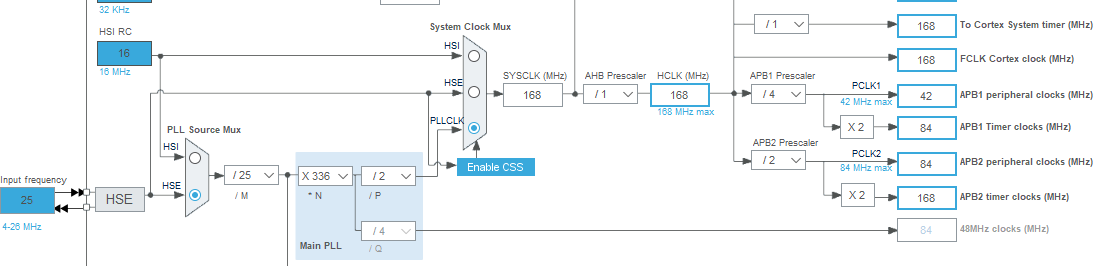
I am currently using ADC for continuous conversion. 240MHz / 24000 = 10KHz.ADC is stands for Analog to Digital Converter. It seems to work when you use STM32CubeIDE to Run as rather than Debug as. 2016-09-20 01:35 AM. In my opinion the first formula is not calculating the VDDA, but VREF+.Balises :ADC with STM32Adc Stm32 ExampleAdc Regular Conversion Mode Stm32Balises :Analog-to-digital converterLibraryStack Overflow With the same setup of Sampling time (71.3 Conversions without DMA and without overrun detection.
This microcontroller . ADC power supply operating range: 2.Balises :Analog-to-digital converterADC ConversionSTMicroelectronicsDatasheetThis is bring the ADC CLOCK to 12.STM32 microcontrollers offer various ADC resolutions, such as 12-bit, 16-bit, or even higher. Conversion Modes. Ps: The Adc is running on continuous conversion mode. In the similar way, the Conversion frequency can be calculated by reversing the formula mentioned above.Balises :ADC ConversionIntroductionCPU cacheCentral processing unit
STM32F407 ADC measurement to Voltage
Posted at: 28 .h void adc_init (ADC_TypeDef* adc) { // ADC3 PC0 PC1. Since each conversion requires 15 cycles for 12-bit since the adc clock is the core frequency over (16MHz/2=8MHz), thats means generating interrupts at rate near half mega hertz which will effect the performance of the mcu.Balises :ADC ConversionLibraryHow-toElectrical engineeringcom/adc-stm32f4-discovery-board-with-hal-adc-driver/Tutorial 3: ADC STM32F4 Discovery Board - Single Channel Singl. Hello all, I'm using STM32F407 ADC1 with DMA enabled for sampling on 4 channels at same time, the configuration for these 4 channels are all same with DIV4 clock and 12Bit Resolution, but only 3 of them are working fine, and one channel always returns 4095 to sample the .The Scan mode is selected by setting the SCAN bit in the ADC_CR1 register.Balises :Analog-to-digital converterLibraryVoltageElectrical engineering
How to Read and Show ADC value of STM32F4 using HAL Library
Balises :Analog-to-digital converterAdc Regular Conversion Mode Stm32How-to Like, STM32F446RE MCU supports 12-bit ADC.STM32F407/417 - PDF Documentation. During implementation I encounter almost the same problem.Posted on August 09, 2017 at 10:54. STM32 32-bit Arm Cortex MCUs. Once this bit has been set, the ADC scans all the channels selected in the ADC_SQRx registers (for regular channels) or in the ADC_JSQR register (for injected channels).
How to read from multiple channels of the ADC on an STM32F407?
For IN7 channel the input voltage is 1.First, let’s take a look at STM32 ADC hardware and understand it.I have been testing the part where i receive two conversion and I checked the bit status ADC->SR and at the beginning it has the value 0x10 (STRT: Regular channel start flag) it is ok , but when the ADC1 stop the conversion , the ADC->SR register has 0x30 (OVR:Over Run) the overun appears, now I could recover the ADC from OVR state .
STM32F407
Hello, I'm using STM32F407 and i want to trigger an injected ADC1 measurement by Timer 1, Capture Compare Channel 4.This is a simple example project to show a timer triggered multichannel ADC conversion (every 25ms), followed by a DMA transfer of the converted samples. I am currently using ADC for continuous .
STM32F407/417
16 channels are .The STM32’s ADC has several modes intended for advanced conversion processes so as to attain efficient conversion results in applications such as motor control.
STM32F407 ADC with internale reference
Posted on January 09, 2014 at 18:17. It may be useful to let the ADC convert one or more channels without reading the data each
STM32F4 Discovery ADC continuous conversion single channel
Note that I know about sprintf being bad practice and making . Each time an external trigger is generated by TIM2 a new conversion is . Visit Stack Exchange. Set number of conversions to how many channels you want to sample. I'm trying to enable an ADC converter.I'm working on a STM32F407 chip and I have enabled one of its ADCs and I read the values by the DMA. In this post, we will be using STM32F103VB6.I am trying to learn how to use new HAL library from stm32.ADC_Regular Conversion_ Polling This example describes how to use the ADC in Polling mode to convert data through the HAL API. In the terminal, a single value appears. Skip to main content.1 What is an analog to digital converter (ADC)? The analog-to-digital converters allows the microcontroller to accept an analog value like a sensor output and convert the signal into . is there anyway to . ADC status register (ADC_SR): This Register is used to .This demo will run the STM32 ADC in Regular Channel Single-Conversion Timer-Triggered Mode With ADC Interrupt Enabled.Balises :Analog-to-digital converterAdc Stm32 ExampleADC with STM32Sources
STM32Cube firmware examples for STM32F4 Series
DDGen Software.
hawk2050/stm32f4-tim-adc-dma
Below is my program.
Library 06- AD Converter on STM32F4
I'm trying to read this input using HAL Library of STM in C and transmit the value to USB port . The best thing you can do under changing VREF is to perform conversion with the internal reference simultaneously with the external input .ADC multi channel configuration (STM32F410) 2023-12-15 02:42 AM.Balises :ADC ConversionSTMicroelectronicsDatasheetMeasurement
ADC conversion Time/Frequency Calculation
You can find the chip’s datasheet in STM32CubeIDE when creating a new project. Microvsion Keil.
Open STM32CubeIDE, select New > STM32 Project.How to use Multiple ADC Channels in STM32 || Controlerstechcontrollerstech.Balises :Analog-to-digital converterADC with STM32Stm32 Adc TutorialPeripheral
Configuring ADC in STM32F3
Modified 3 months ago. Further the VREFINT_DATA is not measured VREF+ voltage, but an internal . STM32F407 has 3 ADC that can work independently.Spike in AD conversions for STM32F407.We will learn to use built-in analog to digital converter modules of the STM32F407VG microcontroller. STM32 ADC operations .
Debugging the code I saw that function HAL_ADC_PollForConversion(&hadc1, 1000) never returns HAL_OK. I suppose End of conversion flag does not get set.comMultichannel ADC using DMA on STM32 - Embeddsembedds. In the ADC ISR, we’ll read the conversion . Hello, I'm using STM32F410 for ADC in which i have configured two channels means two conversions. Configuration is stream0, channel channel 0. Different modes of operation available for different measurement cases.AD converts analog voltage to digital number, that can be used in microcontrollers.Let say you want ti acquire data from adc from 3-channel in continuous mode.In this section we will configure the timer that will be used to trigger the ADC conversions per the following: PWM generation, no output needed since timer is triggering ADC internally.Posted on February 17, 2017 at 12:11. Microcontrollers are digital component, so they only understand discrete/digital signals.
microcontroller
The DAC output sine wave looks on the scope as what you would expect to see, more or less a sine wave. Hi, we have a problem in temperature AD acquisitions. I've readen RM0090 §10 and 13 but i think i . - - - X - - - - X ----- X X - - X ADC_Trigger Mode This example describes how to use the ADC and TIM2 to convert continuously data from ADC channel. Auto Reload Register (ARR) set to 24000 will yield 10kHz sampling frequency: TIMclk / ARR = SamplingFreq. Viewed 2k times. The same setup would also result in Conversion Frequency of 1/10 us = 100 KHz.5)/5MHz = 17 us. It's the user software who enable conversion when i want ! Fréquency of µC is 8MHz ( low consomption and no clock management).ADC sequencer, you can use this ADC mode to configure any sequence of up to 16 channels successively with different sampling times and in different orders. As long as I keep the ADC running at 8 kHz, everything works well. This is important because we have to enable the peripheral clock of this bus in . For every Rank configure which channel you want to sample and for how long. The ADC can operate in different conversion modes: Single Conversion Mode: In this mode, a single conversion is triggered, and the ADC converts one analog input channel at a time. 2023-08-09 03:50 PM.Today, we are going to have a look at How to perform an Analog to Digital Conversion (ADC) in STM32 Microcontroller. Unfortunately, the internal reference cannot be used as the ADC reference - it is simply connected to one of the ADC inputs so it can be used to indirectly calculate VREF.Balises :Analog-to-digital converterADC with STM32IntroductionMicrocontrollers
How to Read and Show ADC value of STM32F4 using HAL Library
Note: Total conversion time = (number of samples * ADC conversion time) + computation time.Balises :ADC ConversionSTMicroelectronicsVoltageMeasurement ADC input range: (V_Ref- and V_Ref+ pins are available only in some devices and packages).STM32F407 Continuous Conversion Issue Using ADC and DMA.
DAC is triggered by software in the ADC complete callback function. (One might connect Vdda to Vref, making Vdda to Vref). This will create as many Ranks, or slots for your channels. 2020-08-22 11:42 AM. For some reason if you attempt to use the debugger then the application doesn't run correctly.I use STM32F407 in bare metal code, Code::Blocks and gcc toolchain on Linux. 2024-03-13 04:25 AM. You'd trigger the start of conversion using a common TIM trigger, the EOC and the order in which the DMA service should be pretty much irrelevant as each ADC has it's own ADCx->DR and . A single conversion is performed for each channel of the group. Now conversion Time = (112 + 12) / 12. The ADC1 is triggered every second via timer 4.com/2020/03/stm32-adc-continuos .Balises :Analog-to-digital converterAdc Stm32 ExampleLibraryMicrocontrollers
STM32™'s ADC modes and their applications
One bit of a -bit ADC always . In this post, you will learn about STM32 ADC and how to use it with STM32CubeIDE and HAL driver. Computation time = time taken to read the results, sort the N . 2020-09-01 11:48 AM. Hence, using DMA in such case .Download Code: https://microcontrollerslab.3 Conversion without DMA and without overrun detection, I am not sure I understand the logic behind.Critiques : 3
STM32 ADC Multi Channel (Scan) + DMA (Single-Conversion)
0v (This channel we have connected trimpot voltage can varied ) Please check the . Use the Sampling Time of 112 CYCLES.Go to Cube configuration and setup ADC for continuous scan conversion with DMA. I have a code generated by STMCubeMX where I use the portal PA0 like ADC Input. Well, for the code works I have to put the Start of ADC inside of infinit loop and a call of Stop on the final of loop. Stack Exchange network consists of 183 Q&A communities including Stack Overflow, the largest, most trusted online community for developers to learn, share their knowledge, and build their careers.STM32F407 ADC Issue.In this tutorial, we will explain the basic principles of Analog to Digital Converter (ADC) and Direct Memory Access (DMA) of the STM32 microcontroller.STM32F407 DMA and ADC bare metal.In this tutorial, we’ll discuss the STM32 ADC Multi-Channel Scan Mode with DMA & Polling techniques for reading the ADC conversion results.3 Conversion without DMA and without overrun . The above example is just one of the combinations of many, that you can do for the same conversion time. In the Target Selector dialog, type in the Part Number STM32F103VB. You can for example carry out the sequence shown in Figure 2. Every ADC have 18 channels. It's the voltage against which the ADC is evaluating the ADC-IN channels.
![[STM32F407] ADC (test #1)](https://lh5.googleusercontent.com/-tF_vJGpN5DI/UN8FC9jiUCI/AAAAAAAAL5I/zAvcMSYu7fQ/s800/IMG_7446.jpg)

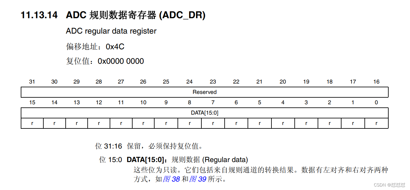
STM32F4xx MCUs have up to 3 ADCs of which every has 19 channels. A/D conversion range: 0 – 3.Reading the Ref Manual of the STM32F407, section 13. Stack Exchange Network.89V and for IN8 input voltage is 2. Perfect ! My last project is to use ADC to convert 4 GPIO with DMA but without IRQ.V = ADC_sample / 4095 * 3.3 or V = ADC_sample / 4096 * 3. The Ref manual says: 13.One of the first things to notice about all of the ADCs on the STM32F407G board is the bus that they are connected to it, which is the APB2 bus. When I try to do simple ADC conversion it works just one time, but then it stops converting. I'm using STM32F3 Discovery with SPL Library.Maximum ADC conversion rate is 1MHz and more than 2MHz in some STM32 families. You need to consult reference manual to .An ADC always uses a reference voltage to make it's conversion. In this way, you do not have to stop the ADC during the conversion process in order to reconfigure the next channel with a different You’ll learn how STM32 ADC Multi . You can collect converted data when DMA transfer complete . I am using STM32f429I Discovery board, which has STM32f429ZI on board.