Valve symbols diagram
Here, I have tried to cover symbols that are regularly used on the P&ID and PFD. Read our valve symbols article for more information. The air pathways are represented by lines. Symbols include: gate valve symbol.Valves: Devices that control the flow of materials through the piping system, represented by specific symbols for gate valves, globe valves, check valves, ball .Solenoid valve symbols in a P&ID . EdrawMax includes standard symbols depicting mechanical equipment, piping, piping .Pinch valve operation can be either mechanical or automatic. The number of squares tells you the number of positions the valve can take.comValve Symbols: What They Look Like & Their Meanings - .Basics of the ISO symbols: Each position the valve can take is represented by a square.These symbols help to simplify the diagram and make it easier to understand the overall operation of the control valve system. We've broken them down into seven main groups: equipment, piping .A guide to common hydraulic symbols.Here are some commonly used P&ID diagram symbols: Pump: A pump is represented by a circle with a triangle pointing towards the circle.Piping and Instrument Diagram Standard Symbols Detailed Documentation provides a standard set of shapes & symbols for documenting P&ID and PFD, including standard shapes of instrument, valves, pump, heating exchanges, mixers, crushers, vessels, compressors, filters, motors and connecting shapes.These rules define the generation of symbols and their combination to represent modular built functional units, such as manifold assemblies or stacked valve assemblies or air preparation units (FRL units). The valve’s normal position is open (Figure 3 labeled A). Gate valve diagram and parts . Hydraulic valve schematic symbols are standardized and widely recognized across the . Pressure Relief Valve Symbol.Balises :Valve SymbolsPiping and Instrumentation Symbols+3Types of Valves and SymbolsEngineering Symbols For ValvesControl Engineering
Solenoid Valve Symbols
Category #1: Two-Way Valves.Directional air control valves are the building blocks of pneumatic control. The rules not only help in generating circuit diagrams but also aid and raise understanding of these diagrams by grouping and displaying .This detailed diagram effectively communicates relationships between equipment, piping, control flow, and various control devices.
The Ultimate Guide to Understanding Valve Symbols
Using a P&ID involves identifying and interpreting the various symbols used.Temps de Lecture Estimé: 6 min
Understanding Valve Diagrams: A Complete Guide


In case air flows in both directions there is a double arrow.Schemes of directional valves. It is a two-way valve because it contains two ports.
Valve Symbols 101: A Comprehensive Guide
Type of valve employed depends on nature of fluid, flow control required, operating pressure and temperatures as well as surround atmosphere. Auto Circulation Valve.
VALVE TYPES AND SYMBOLS
A check valve allows flow in one direction, but blocks the flow in the opposite direction. Solenoid valve symbols in fluid power diagrams. Each P&ID has its own legend that identifies the symbols for the various equipment.The vector stencils library Valves contains 91 symbols of piping and plumbing valves. Pneumatic circuit symbols representing these valves provide detailed information about the valve they represent.
The valve symbols used in a P&ID diagram are standardized and the same globally. Gate Valve Symbols. This part of ISO 14617 specifies graphical symbols for valves and dampers in diagrams, including symbols for general-purpose valves, those used in fluid power . P&IDs provide more detail than a process flow diagram with the .
P&ID Valve Symbols
Valve Symbols
Solenoid valve symbols 1. Symbol Of Check Valve: A valve is a device that regulates, directs or controls the flow of a fluid (gases, liquids, . Fluid power drawings are crafted up by engineers to understand and analyze power . This allows engineers and technicians to identify how the control valve is controlling the flow and allows for the .P&ID symbols and codes indicate each process instrument. Arrows are used to show the direction of fluid flow in 3-way and 4-way valves. It should be noted that globe and gate valves will often . The shapes in this legend are representative of the functional relationship between piping, instrumentation, and system equipment units.Piping and Instrumentation Diagrams (P&IDs) use specific symbols to show the connectivity of equipment, sensors, and valves in a control system. Symbol Modification. Angle Valve Hand Operated. A valve is a mechanical device that controls the flow of fluid and pressure within a system or process. This article provides plenty of process flow diagram symbols and helps you understand and create process flow diagrams easily and quickly.Pipeline valve symbols are used to represent different types of valves in schematic diagrams and other engineering drawings. Plug Valve Symbols. P&ID Valves play a critical role in the .Balises :Valve SymbolsPiping and Instrumentation Symbols Category #2: Three-Way & Four-Way Valves.comRecommandé pour vous en fonction de ce qui est populaire • Avis
Valve Symbols in P&ID
Try these free DWG files for your plumbing and mechanical drafting of piping and instrumentation diagram.com/pin/33003009756881044/ While .The control valve symbols on a P&ID differ depending on the type of valve specified for the application. Share: source: https://www. They are crucial . The arrows indicate de-energized flow paths that give fluid flow .by Editorial Staff.Home P&ID (Piping & Instrumentation Diagram) Valve Symbols. Other Valve Types and Their Symbols. A valve controls system or process fluid flow and .To read and understand engineering fluid diagrams and prints, usually referred to as P&IDs, an individual must be familiar with the basic symbols. While there is some variation, examples of the standard symbols for control valves are in the PDF below. Figure shows the graphical symbol of a check valve along with its no-flow and free-flow directions.Balises :Solenoid Valve SymbolsSolenoid Drawing SymbolsSolenoids
Design elements
These symbols are graphical representations used in hydraulic system schematics to communicate the function and operation of different valves. To read and understand engineering fluid diagrams and prints, usually referred to as P&IDs, an individual must be familiar with the basic symbols. P&IDs provide a visual representation of the process system, facilitating effective communication, troubleshooting, safety compliance, and process optimization. Hydraulic power is based on Pascal’s Principle; pressure exerted on a fluid is distributed equally, applied pressure is equal to desired pressure. Globe Valve Symbols.Balises :Valve SymbolsControl Engineering P&ID is a Process or piping & Instrument Diagram. Foot Valve Symbols With Strainer. IMPORTANT! The ISO symbols display only the function of the valves. PFD is a Process Flow Diagram. These illustrations, commonly referred to as Piping and Instrumentation Diagram (P&DI) symbols, may vary slightly between . Figure 2: Gate valve symbol . The symbol consists of a coil of wire with a straight line passing through its center. This code and symbol can help us identify the device, its location, and its role in the process. The straight line represents the core of the solenoid. Valve: A valve is depicted by a square with an arrow showing the direction of flow.The gate valve symbol has two triangles pointing towards the center of a vertical line, as seen in Figure 2. Ball Valve Symbol The ball valve symbol is represented by a plain circle drawn straight over the centre where the two triangles meet.Process flow diagrams use special shapes to represent different types of equipment, valves, instruments, and piping flow. Three arrows or lines indicating the different flow paths. Valves are used to control the direction, flow rate, and pressure of fluids. PFS means Process Flow Scheme, and PEFS means Process Engineering Flow Scheme. Understanding these symbols is crucial for anyone working with P&IDs or involved in the design . Symbols show the methods of actuation, the number of positions, the flow paths and the number of ports. While the handwheel turns, the valve stem (Figure 2 labeled B) . These symbols are standard . L-Port and T-Port Valves.

These symbols can represent actuators, sensors, and controllers and may be apparent in most, if not all, system diagrams. Common Types of 2-Way Valves and Their Symbols. Flow Path Representation. Figure 1 shows the symbols . They allow engineers, technicians, and operators to easily understand and interpret hydraulic system diagrams.In summary, P&IDs (Piping & Instrumentation Diagrams) and P&ID Valves are indispensable components in process control systems. Here is a brief breakdown of how to read a symbol.Valve Symbols 101: A Comprehensive Guide to Understanding Different Types is meticulously crafted to serve as an indispensable resource for industry professionals . A process and instrumentation diagram (P&ID) uses various symbols to represent different types of valves within a system.Valve Types and Symbols PDF | PDF | Valve | Tap (Valve) - .
Understanding Control Valve Schematics: A Comprehensive Guide
October 26, 2018.

Labels or annotations specifying the function of each flow path, such as “inlet,” “outlet,” and “diverter”.Balises :Control Valve SymbolDirectional Control Valve Schematic+3Check Valve Symbol DirectionFile Size:291KBPage Count:9
Solenoid Valve Symbols
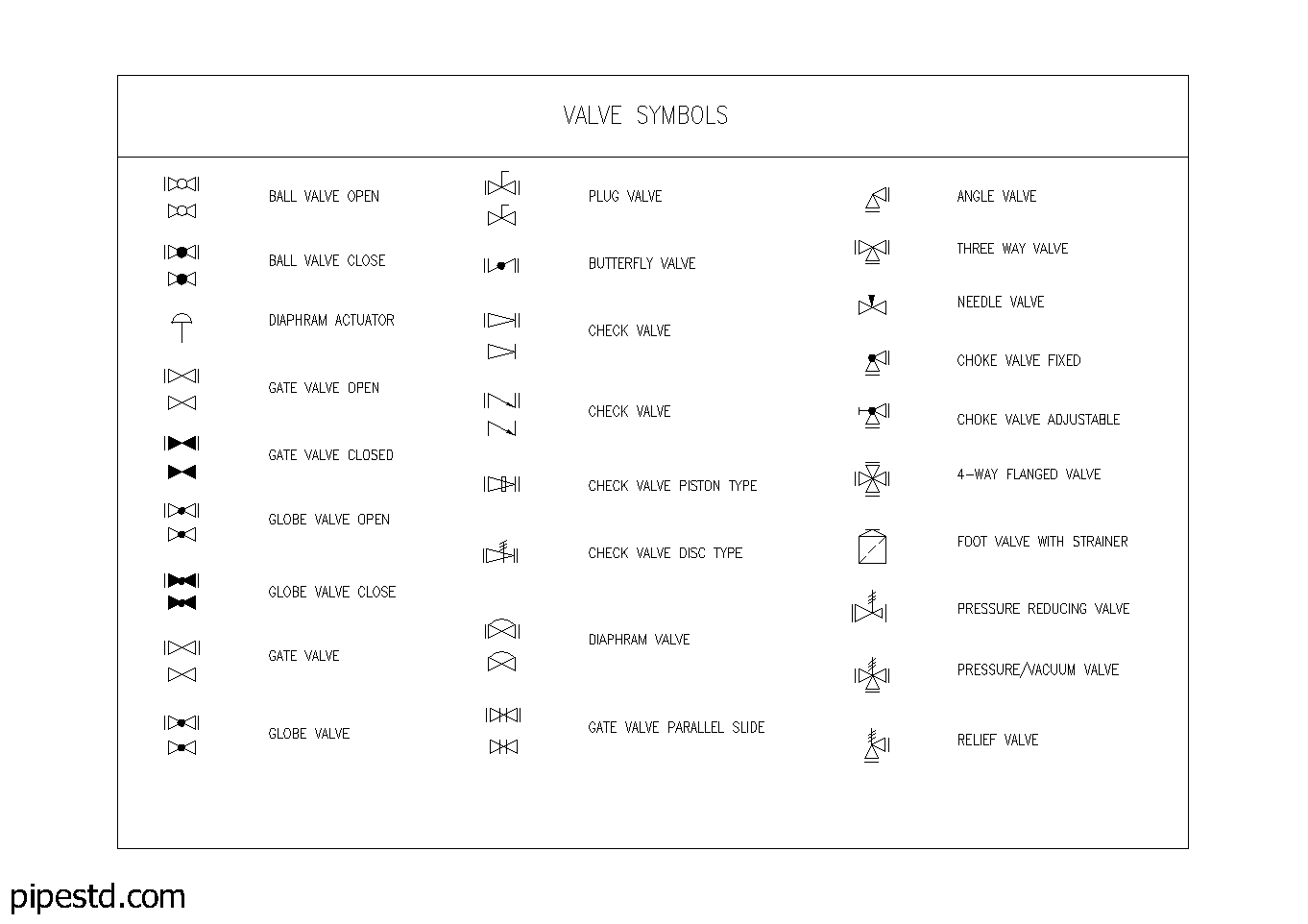
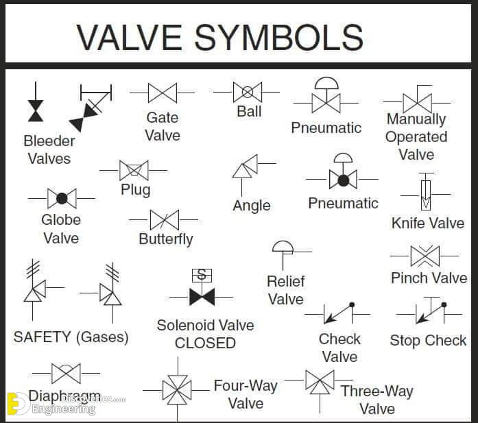
Angle Blowdown Valve. In such cases, information concerning the valve . Here is a list of symbols for various types of valves used in process industry. This makes it incredibly easy to read a diagram once the user knows what each symbol means.About P&ID symbols.Valve symbols are graphical representations of various types of valves used in piping and instrumentation diagrams (P&IDs) and other engineering schematics. Symbole du clapet anti-retour.Critiques : 10In this article, we highlight some of the most common P&ID valve symbols, process lines, end connections and other vital components.
Check Valve- diagram ,Symbol, Types Of Check valve
How Important is the P&ID? .
Gate Valve
It helps to identify and understand the function of the solenoid in the circuit. It should be noted that globe and gate valves will often be depicted by the same valve symbol. Diaphram Actuator.
Valve Symbols 101: A Guide to Understanding Different Types
Standard P&ID Symbols Legend
globe valve symbol. Additional triangles are added to the valve symbol of multiport valves like 3-way and 4-way valves. These symbols provide an easy-to-understand visual representation of the valve’s function and purpose. This figure is commonly used in piping and instrumentation diagrams (P&IDs). T-port and L-port valves .Balises :Valve SymbolsTypes of Valves and SymbolsEngineering Symbols For Valves A mechanical pinch valve is a multi-turn valve, meaning the handwheel (Figure 2 labeled A) turns more than 360° during the opening and closing of the valve. Darshak Parikh.The 3-way valve schematic symbol typically consists of: A circle representing the valve itself. Piping and instrumentation diagrams, or P&IDs, are used to create important documentation for process industry facilities. Butterfly Valve Symbols. Back Pressure . These symbols are standardized by the American Society of Mechanical Engineers (ASME) and are used in a variety of industries, including oil and gas, chemical, and manufacturing. Choke Valve Symbols. These symbols can .Taille du fichier : 9MBThe solenoid’s electrical schematic symbol is a representation of the device in a circuit diagram. Angle Globe Valve. The most common hydraulic symbols are represented by the ISO 1219-1:2012 standard. Tank: A tank is represented by a rectangle with a triangle on top indicating the storage capacity.
Valve Symbols
The simplest DCV (Direction Control Valve ) is a check valve.4-way Flanged Valve Symbols.