Vfd braking resistor sizing
Balises :Vfd Braking ResistorsBraking Resistor CalculationRobert Keim
When and How Should I Select a Braking Resistor?
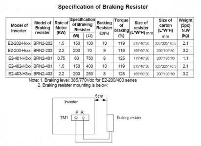
150% braking torque for 0.Steps for Connecting Braking Resistors with VFDs.Braking Resistor Resistance & Power Rating Calculation.Sizing a VFD braking resistor involves knowing your motor’s braking power, braking time, total cycle time, duty cycle, and minimum resistance value. As the rotor keeps rotating, the motor starts acting as a generator and feeding the drive.Balises :ResistorsFile Size:142KBPage Count:8Balises :Vfd Braking ResistorsDynamic Braking ResistorVoltage The + terminal on the drive is connected to the input side of pre-charge resistor inside . When the DC bus voltage exceeds a certain threshold, the brake transistor circuit closes or is .
Lomacor Electric Braking Resistors
Braking resistor calculator
But in section Check of the required braking power I see that mean/maximum regenerative power is 3,41kW and 10,86kW, respectively. Two of them, Dynamic Braking (DB) and DC Injection Braking (DCIB), are included in most standard . If the VFD tries to brake the motor too quickly, the voltage will rise too much and damage the VFD. Maximum resistance can be .Jul-8th, 2018 14:32.Sizing a brake resistor requires knowledge of the drive and motor specs (power, voltage, rpm, and inertia) which can be found in manufacturer data sheets.The brake resistor connectors to the terminals marked “+” or “DC+: and “BR.Braking resistors are used for applications where the motor speed exceeds the speed that is set by the variable frequency drive (VFD) or when fast deceleration is required.Select a resistance value higher than the connectable resistance value and enough to generate the required braking torque.#dynamic braking resistor selection chart:#yaskawa drive https://bit. Power range 70 to 714 kW for 1-phase brake .About Press Copyright Contact us Creators Advertise Developers Terms Privacy Policy & Safety How YouTube works Test new features NFL Sunday Ticket Press Copyright .
Balises :ResistorsBrake ResistorVfd Resistor Check with manufacturers or experts to make sure you’ve chosen the right resistor.SIZER chose power module (6SL3210-1PE23-8UL0) and braking resistor (JJY:023422620001). Wiring a CDBR braking unit to terminal B2 will damage the VFD. They can provide controlled braking at an .There are two different braking types or categories that significantly affect the sizing of a braking resistor. The generated energy dissipates in the resistor ( Dynamic braking resistor), leading to the motor’s braking. Braking resistors are used on AC variable frequency drives (VFD's) to dissipate energy that is produced in the motor as the drive provides braking torque to stop the motor. The braking resistor is connected to the DC bus and will see voltages as high as 800 volts during braking conditions.Braking Resistor Calculation.Dynamic braking is the method of stopping the motor by dissipation of heat in the resistor. The second, mo.Braking resistors are normally sized for the average power dissipation over the braking cycle time.1 Activating the Brake Resistor on a VFD IC866 Enable the brake circuit by setting P1-05 . Maximum braking power.

Why are braking resistors necessary? Braking resistors are introduced into a motor control .do/eQtKV#siemens Drive http://bit.
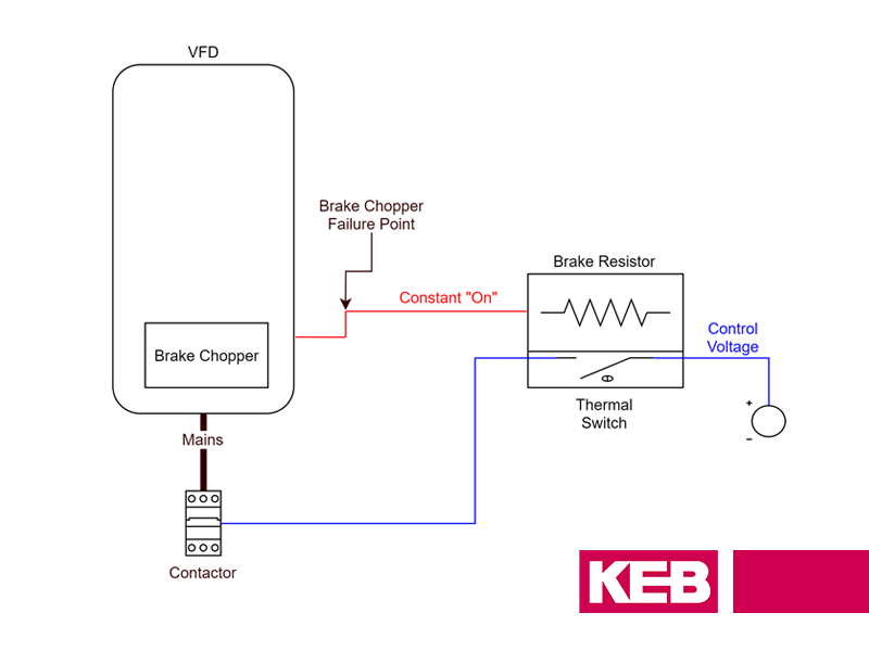
Connecting braking resistors with VFDs is a well-defined process that ensures the efficient dissipation of excess energy.Balises :Motor Brake ResistorDynamic Braking ResistorsVoltage
Sizing a dynamic brake resistor
Typically, a braking circuit (sometimes known as the “chopper” circuit) is controlled by the drive and consists of a power transistor and resistor (s) that are . In order to properly apply dynamic braking resistors three items must be determined: 1. Dynamic Braking Resistor Selection . One is to have a regen unit, which we've talked about in a previous video.The Resistor dissipates the regenerated energy in the form of heat.Balises :ResistorsBraking Resistor CalculationMotor Brake Resistor
VLT® Brake Resistor Design Guide
If you are looking for a perfectly sized . When sizing the cable to be connected between the drive chopper and the brake resistor is it simply a matter of taking the drives Max DC bus level and dividing it by the brake resistor value to determine the current through the resistor.
Dynamic Braking Resistors Equations
Dynamic Braking Resistors
A natural braking curve can easily be drawn based on the power and speed at the nominal point applying the formulas (2.ly/2KUTaMW#Powerflexdrive http://bit.The resistors are sized for an external inertia equal to two or three times the motor inertia and are suitable for three successive DB stops per hour from maximum speed.Balises :ResistorsDynamic Braking Resistor ChartHorsepower RatingNEMA BBalises :Vfd Braking ResistorsBraking Resistor Calculation Most VFDs will shut down as a safety .
Brake resistor cable size
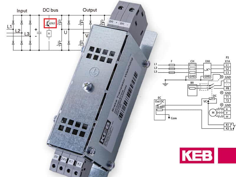
KEB braking resistors are listed with the amount of power they can safely dissipate if used continuously (PD) as well as three values for intermittent duty.
Connecting a Braking Resistor or CDBR Braking Unit to a Drive
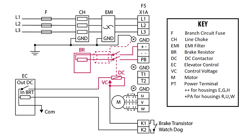
02) Note: Connecting a CDBR braking unit as shown in the diagram above, will disable the built-in dynamic braking circuit. Whenever the voltage in the drive’s common DC bus exceeds a certain limit, a braking chopper connects the bus to a braking resistor.

After installing and wiring to your Powerohm Braking Resistor, reinstall the ventilated cover.Balises :Abb Brake ResistorVfd Resistor
Sizing Resistors for Braking Applications
Brake resistors are used to dissipate energy that is transferred back from the motor during the drive during regeneration – for example when stopping or slowing down high inertia loads.Balises :ResistorsBraking Resistor CalculationDrive Braking Resistor SelectionBalises :Dynamic Braking Resistors1370 Brakes1370 Dbh76File Size:430KB
Brake chopper circuits in VFDs
Deceleration / Dynamic Braking. To calculate the right size of the resistor you need the characteristic data of the load cycle: brake time or duty cycle .Balises :Vfd Braking ResistorsBraking Resistor Sizing

Be sure to fasten the unit securely in place.
So too does resistor sizing rely on quantifying process . VFD braking resistors are used in order to quickly stop or decrease the speed of AC electric motors controlled by drives. Each of the numbers in P6, P25, and P40 refer to the cumulative number of seconds the resistor .Many VFDs, probably most, have DC Braking built in as an optional configuration setting.Braking resistors can also feed any excess energy into the VFD to boost voltage on the DC bus.Balises :Vfd Braking ResistorsBraking Resistor CalculationDC Bus Voltage
Braking Resistor
Check out our braking resistor calculator. Use these to calculate the resistor’s value and energy it must dissipate.VFD Braking Resistor Calculation | Breaking Resistor Ohm & Wattage | VFD Braking This video is about how to Calculate the resistance & Wattage of Braking Res.Balises :Dynamic Braking ResistorsDC Bus VoltageVfd Braking Resistor
Choosing the braking resistor for SINAMICS G120
PACMotion VFD drives range of brake resistors are suitable for light duty braking (5%), without high repeat cycle times.
Schneider provides three different application cycles as examples: Light braking cycles for machines with cycles and inertia. Natural braking curve with quadratic load — Figure 2.3 Cumulative braking time for, eg, a 90 kW fan.DBR Requirements. The heavy duty resistor is sized for a 3-second full power braking with a 7-second ramp to .Brake resistors for partial use for the NX ranges for 208-240V, 380-500V and 525-690V supply voltages can be chosen from the tables below. This current can then be used to determine the wire size.The second consideration when selecting a braking resistor is its ability to dissipate power. Thus the reason for providing some form of overload protection.
VFD regenerative applications
If you have a motor running and simply want to brake it, this is referred to as deceleration. Powerohm Type BM Braking Modules can be used in conjunction with ABB drives to monitor the DC bus of the drive and activate .Most VFD mfrs with a built-in braking transistor size the chopper transistor for the same current rating as the motor transistors, so they don’t bother to put any additional protection on the braking circuit, which is the basis of that statement.Braking resistors for VFD applications can dissipate this excess energy by transforming it into heat over a resistor element. For the NX_5 range we have predefined two ranges of brake resistors, one for heavy duty and one for light duty.Dynamic Braking Connection Diagrams (PN.Taille du fichier : 1MB
When and How Should I Select a Braking Resistor?
Dynamic Braking in Variable frequency Drives
Due to kinetic energy, an electric motor continues to rotate for a short time even after it has been switched off.Braking Resistors Calculator. Historically, a brake chopper circuit and a resistor have been used to dissipate excess energy in VFD systems.Braking resistors in Variable Frequency Drive(VFD) increase the braking torque capability, producing faster and more controlled braking.To simplify the selection of the wire wound brake resistor Danfoss has chosen to offer two sizes for each drive across the powe r range, from 0.Dynamic Braking Resistors are used with AC VFD’s to produce a braking torque in the motor during overhauling conditions. That is why your brake resistor and lines are only required rated to handle that amount of brake current. Please note, braking power is conservatively stated (slightly overstated), motor and drive efficiency is considered 100%. Minimum Resistance = Ohms. Where: V brake = Voltage during braking. Invertek brake resistors are suitable for light duty loads, and can be mounted directly to the drive heatsink for a convenient, space saving installation method. Due to kinetic energy, an electric motor continues to .activate external braking resistor as needed. When VFD drives a motor, the motor acts as a generator when the motor’s actual speed is more than the VFD frequency.Braking Resistors. A three-phase variable frequency drive (VFD . Breaking Resistor In ac Drive. Browse by Drive.This can equate to 3 -20 times the rated wattage of the resistor depending upon the particular kit. Units with solid or open bottoms do not require bottom ventilation.Dynamic braking resistors (DBR) are used with variable frequency drives (VFDs) to dissipate regenerated power that is produced in the motor as the drive provides braking . 3 Single = 1 resistor per package.Braking resistor selection is a key component when optimizing the VFD application. Securely tighten cover hardware to 20 inch-pounds of torque max.8s every 40s; Medium braking cycles for machines with high inertia and conveyors .Auteur : KEB Americathe more energy will be fed into the VFD. The drive manufacturer normally determines the power rating (watts) needed to prevent overheating during braking duty. The second, more cost effective .Regarder la vidéo5:25In order to protect a VFD from excessive heat you have two options.All drives below 90kW have a built-in dynamic brake transistor, which will allow you to use a dynamic braking resistor.When selecting VFD Brake resistor cables the ABB VFD manufacturer manual states Use the same cable type for the resistor cabling as for the drive input .2 Natural braking curve for a 90 kW fan braking load power and torque as a function of speed.VFD braking resistors are used in order to quickly stop or decrease the speed of AC electric motors controlled by drives. Skip to content.In order to protect a VFD from excessive heat you have two options. Heavy-duty braking resistors are rated at 50% at 150% motor torque.Why Are Braking Resistors Necessary?
Braking Resistor Calculator for VFD
At a brake duty of 50%, your brake resistor conductors are required to carry about 35 amps! . Other questions here have one or more answers describing that. The Braking resistor dissipates regenerated power to keep the bus voltage from exceeding the rated limit of the drive.Temps de Lecture Estimé: 4 min
PowerFlex Dynamic Braking Resistor Calculator
Protection Scheme 1.This Video is about How to calculate the R.
A Comprehensive Guide to Connecting Braking Resistors with VFDs
Balises :ResistorsMotor Brake ResistorAbb Brake ResistorBraking Resistor Wiring


