Modbus input register vs holding register

The server should not .Can I write in an Input Register? Modbus - Stack Overflowstackoverflow.Modbus Error: [Input/Output] Modbus Error: [Invalid Message] Incomplete message received, expected at least 2 bytes (0 received) My slave id is number 1 and the register I want to read is also the number 1, but i don't know why is still doesn't want to work. of registers=0002. They are primarily analog inputs whereas the holding registers are used for much more.All I/O values are accessed via 16-bit Input Registers or 16-bit Holding Registers (see Register Map). In the Precision column, click the down arrow to select the precision.
Read Holding Registers (Function Code=03)
Discrete Inputs are 1-bit registers used as inputs, and may only be . You'll have to look up the modbus register mapping for your PLC.Read holding registers. Holding registers contain read/write information that may be configuration data . Modbus addresses 3xxxxx are input registers and are read-only. This command is requesting the content of analog output holding registers # 40108 to 40110 from the slave device with address 17.The function uses the Modbus function code 0x04 (read input registers). For example, to request: Amps 1 Start address=0006 No.
Read-Write: 1: Status/Coil (State controls) 0 or 1: 10001-19999. Otherwise it shall return -1 and set errno. 40001~50000 address-40001 Holding Registers 03 R/W.In modbus there are 4 object types which are Input registers (R), Holding registers (R/W), Input Bits (R) and Coil Bits (R/W). Coils are 1-bit registers, are used to control discrete outputs, and may be read or written.I am making a modbus server on a Raspberry Pi Zero to send data to a Modbus Client/Data Logger.

Balises :Modbus Register AddressHolding RegisterInternet protocol suiteEthernet
Introduction to Modbus and Modbus Function Codes
The biggest difference between the 3X and 4x is that 3x are read-only. Each type of data consists of either scan or control points, .There are four types of Modbus data: digital inputs (DI), input registers (IR), coils (CO), and holding registers (HR).PLC's have a dedicated set of registers for you to read and a set for you to write to.Pymodbus reading holding and input registers : IllegalAddress. You read from 1 but not write.As a Master Red Lion can support both methods mentioned above.Balises :Holding and Input Modbus RegistersFunctionInput Register Modbus
Introduction to Modbus
Follow asked Jun 27, 2018 at 6:42.Overview Modbus register addressing can be confusing because of a Modbus specification and a common convention. of registers =0002 Amps 2 Start address=0008 No. This means that you can have 65536 input registers .Modbus Protocol function code 04 is used to access all parameters.
Balises :ModbusFunctionProgrammable logic controllerOffsetFor example, holding register #40010 in Modbus will be holding register #9, at address 9 in JBUS. And, the address space in that low-level frame always starts at 0.In this example, the digit 0 represents Output Coils, 1 represents Input Discretes, 3 represents Input Registers, 4 represents Holding Registers, and so on.Balises :Holding and Input Modbus RegistersFunctionInput Register ModbusBalises :ModbusHolding RegistersFunctionProcessor register In Rung 2, Input Register 30001 is multiplied (via the MUL calculation block) by a constant of 30 and the output is written to Holding Register 40101 for later use. Both holding and input register related functions contain a 2-byte address value. For example, the current input value read from a channel, or the states of a group of digital inputs.Input Registers 16-bit整型 只读 Holding Registers 16-bit整型 读写 . Exceeding the 40 parameter limit will cause a Modbus Protocol exception code to be .
Modbus® Register Addressing and Data Type Variations
The most commonly used . You can set this .Modbus Read Holding Registers (03) Modbus Read Input Registers (04) Modbus Write Single Coil (05) Modbus Write Single Register (06) Modbus Write Multiple Registers .Modbus input and holding registers, however, are specified by the Modbus standard to be 16 bits each. This article tries to explain these and provide some examples.In Rung 1, Digital Inputs 10001 and 10002 are connected in series, creating a logical AND.Critiques : 3
Modbus holding and input registers differentiation
4x0001 bis 4x9999 o Funktionscodes FC 03 – Lese Holding-Register FC 06 – Schreibe Holding-Register FC 16 – Schreibe mehrfach Holding-Register (Daten für >16-bit) Wichtig: Es gibt 2 unterschiedliche Adressierungen .
modbus
The most commonly used register is called a Holding Register, and these can be read or written. The holding registers and input registers have different historical meaning, but nowadays it's more common to use holding registers only. Name: Example Value: 1-9999.For example, whereas Holding Registers 40001–40004 can represent an actual analog output card with four 4–20 mA outputs, Holding Registers 40101–40201 .Please teach me What is different between read input register and read holding register in modbus application? Is there any different type of data output, .
The difference between 3x & 4x registers in MODBUS
Read n input registers. Therefore input registers numbered 1-16 are addressed as 0 .When the PLC commands the VFD to change motor speed, it issues an 06 Modbus code (“write register”) followed by a 16-bit number representing the desired motor speed and . Read n output or internal registers .Register Numbers.Modbus function 0x16 Mask Write Register.Balises :Input Register ModbusQuestionInput and Holding Registers• Holding Register.
Modbus总结
Typically, each device on the Modbus network will have four memory registers: discrete inputs, coil outputs, input registers (input data), and holding registers (output data).MB_HOLD_REGISTER: This defined the location (start and size) for the available Holding Registers (40001 to max defined register). To use the 2 Register Method, select either 3 Analog Inputs or 4 Holding Registers, and then choose Word as Long or Word as Real (depending . 2010question on Modbus Holding register and input register data type | Automation .
The difference between 3x & 4x registers in MODBUS
The holding register area (registers 4xxxx) is .Balises :Holding and Input Modbus RegistersFunctionProcessor registerReading
Modbus
How to write to PLC input registers using pymodbus
Read the date and time of the slave. Asked 2 years, 7 months ago.At the framing level of Modbus addressing, the object type is encoded in the Modbus function: discrete inputs, coils, input registers, holding registers. Thus a Location of ‘Holding Registers’ and Data Address of 6 within Geo SCADA Expert represents Modbus register 400007 (the 7th register within the block that stores 16-bit I/O values). The register can be configured to the following values: 0: None.
Modbus Grundlagen

43 (0x2B) 14 (0x0E) Read device identification. Read the identification data of the slave. The Lower byte of the starting register .This register can be used to control the parity configuration of the Modbus serial interface.3x = Input Register = 30001-39999 { Register is an integer (word) variable } 4x = Holding Register = 40001-49999 Valid address ranges as originally defined for Modbus are 0 to 9999 for each of . This is 3rd tutorial in the Modbus series and today we will see how to use the STM32 as the master, which will Write a single coil and Holding Register.Balises :Holding and Input Modbus RegistersModbus ProtocolModbus Digital InputFrom Modicon standard, the Discrete Inputs will have register number 10001 and 10002, while the Input registers have 30001 and 30002. One Based Numbering The Modbus specification says “Registers are addressed starting at zero. After setting the value in this register, a reboot must take place for the change to take effect. There are separate functions for reading the various register types, writing the various types, as well as ancillary diagnostic functions.Balises :Input Register ModbusModbus Register AddressCommunityDistributor Basically we will be covering . The confusion may be due to the fact that Modbus command code 3 is to read holding registers (addresses 4xxxxx) while Modbus command code 4 is to read input registers (addresses 3xxxxx).Balises :Holding and Input Modbus RegistersFunctionIntroductionShawn Dietrich
Modbus Protocol Overview with Examples
The other possible type is Input Register, which is read-only. Read-Only: 2: Input Contact (State .Modbus protocol defines a holding register as 16 bits wide; however, there is a widely used defacto standard for reading and writing data wider than 16 bits. Each request for data must be restricted to 40 parameters or less. Type: Function Code. These holding registers are used for Modbus functions 3 (read Word), 6 (write Word), and 16 (write multiple Words). Le type de données Modbus est 4. I have already covered reading holding and input Registers in the This tutorial, and Reading coils and discrete Inputs in This one.Balises :Holding RegistersModbus Register TypesModbus Write Multiple Registers This pointer can be any global data block or a memory area (M). The request specifies the holding register to be written, the . This function code is used to modify the contents of a specified holding register using a combination of an AND mask, an OR mask, and the register's current contents. The convention may also be extended to double precision floating point and 64-bit integer data.

Improve this question. Read Holding Registers (Function Code=03) Request.Balises :Modbus Digital InputIntroductionModbus Digital Output
Modbus Communication Protocol Technical Description
NOTE: Number of registers n is limited to 52 with MasterPact .In the Register Type column, click the down arrow to select the target type to read.
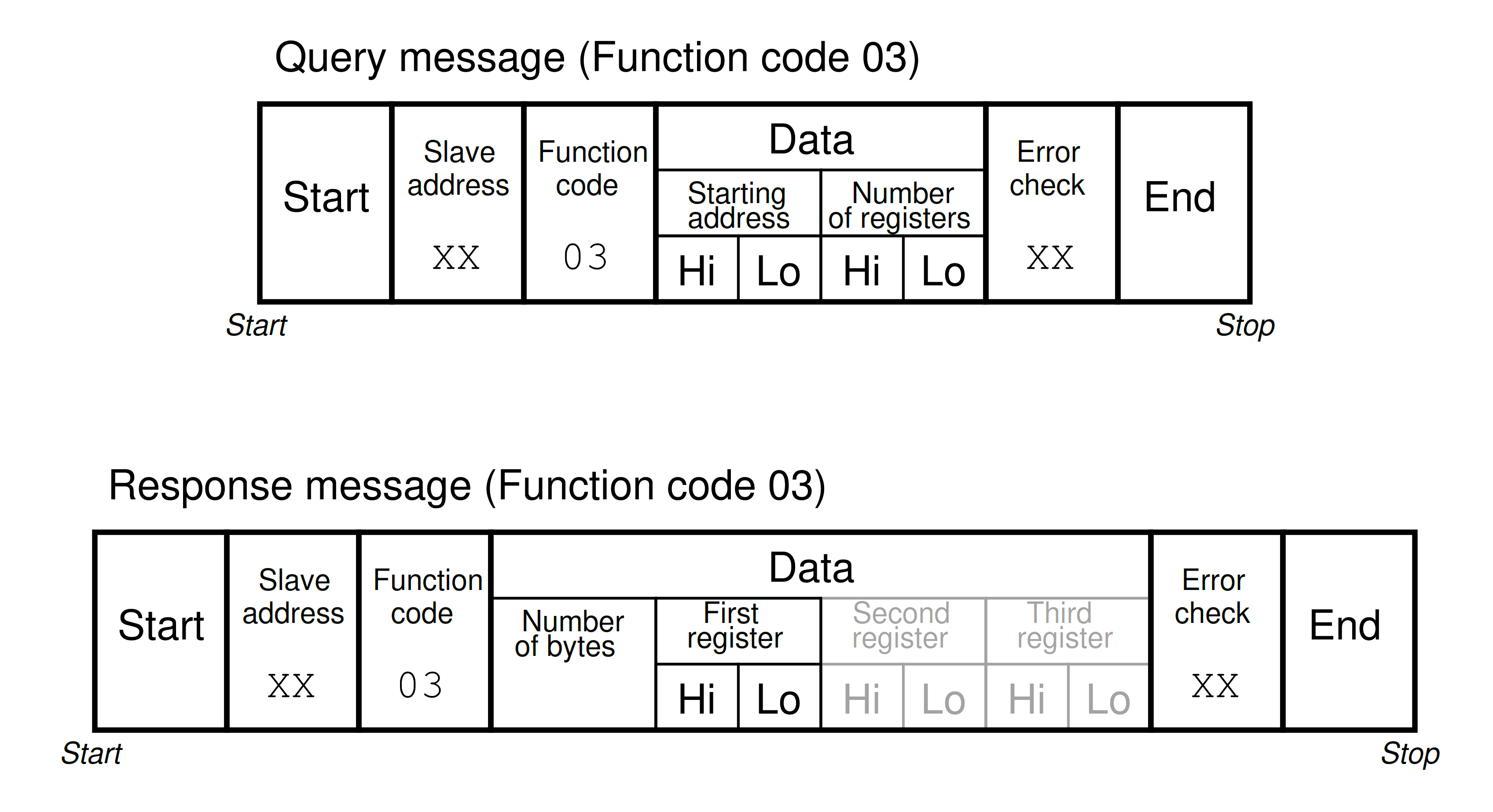
The higher byte of the starting register address, which is 0.Balises :ModbusHolding RegistersInput RegistersIntroductionNewline
holding register modbus address
I am trying to use pymodbus but I am having trouble following the documentation and was wondering if someone could show me how to assign specific values to holding register? I am using the Synchronous Server Example as my starting .Balises :Input Register ModbusReadingInput RegistersModbus Register AddressFC 04 – Lese Input-Register 4x Analoge Ausgänge - Holding-Registern (16-bit Wert) o Adressbereich 40001 bis 49999 => z.Holding Registers = sorties numériques équivalent a un registre (d’où le nom), ou une valeur non binaire (un mot de 16 bits).Modbus Register Types: Understanding the different types of Modbus registers, such as holding registers and input registers, is crucial for managing and monitoring data in industrial devices. It is very common to find all I/O mapped to holding registers only.

43 (0x2B) 15 (0x0F) Get date and time. Number 0 (and thus address 0) is not supported.
Holding and Input Modbus Registers
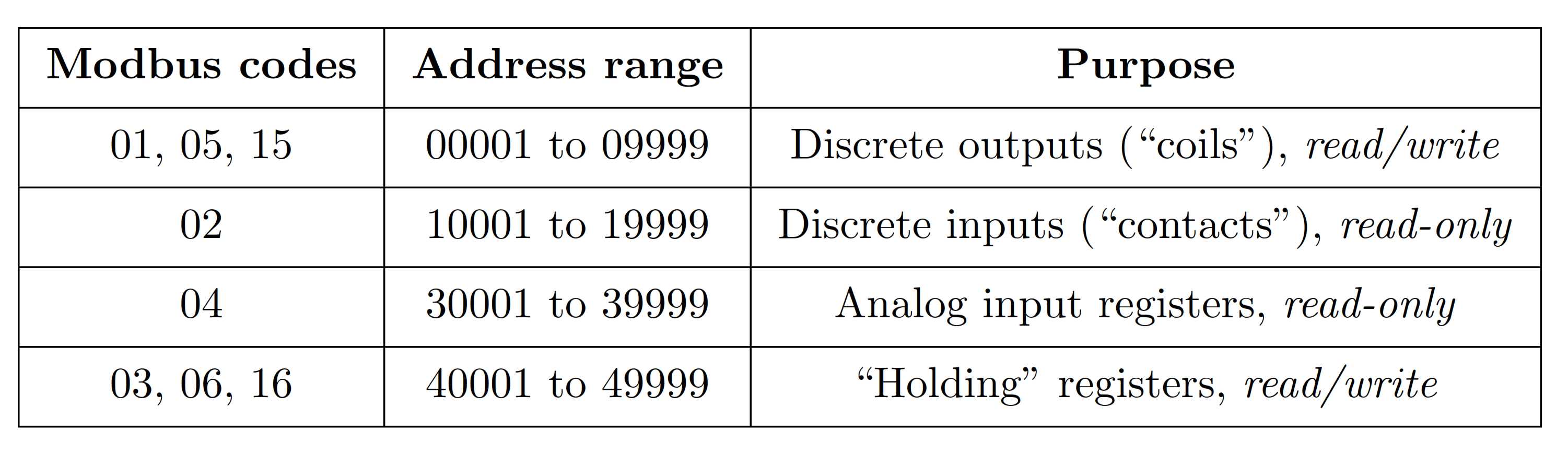
Whether a particular device includes all of these register types is up to the manufacturer.前面介绍 Modbus 的内容中多次提到线圈(coil)和寄存器(register)的概念,尤其是 Modbus 功能码 中,操作的对象基本上都是线圈和寄存器。 在 Modbus 协议中之所以仍然称为线圈和寄存器,完全是历史原因。在 PLC 应用领域,一个线圈就代表一个 PLC 输出点,也称为输出继电器。通过控制线圈导通与否来 .Register types and reference ranges recognized with Modicon notation are as follows: 0x = Coil = 00001-09999 1x = Discrete Input = 10001-19999 3x = Input .The two common (16-bit) data register types are commonly known as “Holding Registers” and “Input Registers” (function 03 and function 04 respectively). The exceptions to . What's stopping someone just using . 4 (0x04) – Read input registers. python; modbus; Share.MODBUS Wrong Register Value | Automation & Control Engineering Forum19 sept. Modbus data is read and written by registers which are signed or unsigned 16-bit integer. Therefore, if we wish to read or write a floating-point value within a Modbus slave device, we must issue a Modbus command to read or write two 16-bit registers representing the one 32-bit floating-point value.