Simulink outport block

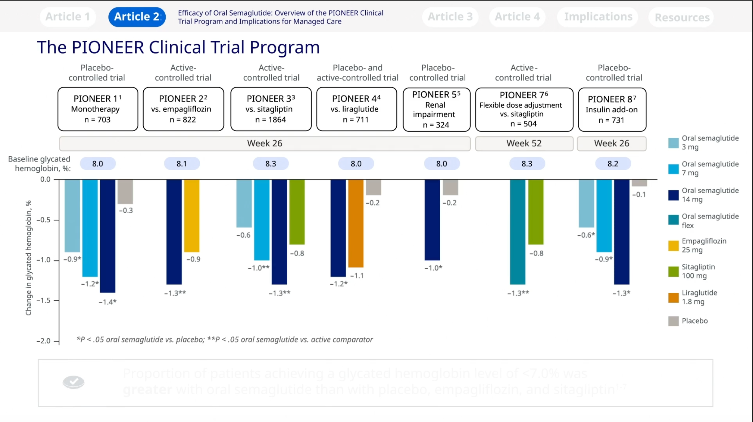
For example, if the input vector is [18 15 17 10] and the control input is 3, the element that matches the .Outport 模块将信号从系统内链接到系统外部的目标。 它们可以连接从子系统流动到模型其他部分的信号。 它们还可以在模型层次结构的顶层提供外部输出。 Outport 模块端口号 .This table lists the properties common to all Simulink ® blocks, including block callback properties (see Customize Model Behavior with Callbacks).
Bibliothèques de blocs
The output changes no faster than the specified limit. For simulation time greater than or equal to the Step time, the output is the Final value parameter value. Examples of commands that . Then, choose one of these techniques: Display the dimensions directly on the block diagram. The Symbols pane displays the variable names in the Name column. The Connection Port block transfers a physical connection or signal across subsystem boundaries. An input/output relationship fully characterizes a block.
For more information, see Initial Block Output. The Multiplication parameter lets you specify element-wise or matrix multiplication. To generate data using devices that do not support clocking, use the Analog Output (Single Sample) block. Consider logging output data in a top-level model when your model already includes an Outport block. You can use these shortcuts to connect .
The Integrator block integrates an input signal with respect to time and provides the result as an output signal. When a Merge block . To learn about data integrity and deterministic data transfer . The Step block provides a step between two definable levels at a specified time.In Simulink ®, signals are the outputs of dynamic systems represented by blocks in a Simulink diagram and by the diagram itself. Output data logged in Dataset format streams to the Simulation Data Inspector during .
Use of Inport and Outport blocks in Simulink
For an introduction to RF simulation, see the example, Simulate High Frequency Components.Bus オブジェクトをデータ型として指定する場合、 Outport ブロックの一部のパラメーターは無視されます。 たとえば、 Outport ブロックの [最小値] 、 [最大値] 、および [単位] のパラメーターは無視されます。By default, the Relational Operator block compares two inputs using the Relational operator parameter that you specify.
Getting underlying Subsystem Inport/Outport Block via Port Handle
Simulink assigns Outport block port numbers according to these rules: It automatically numbers the Outport blocks .An Index Vector is a special configuration of a Multiport Switch block in which you specify one data input and the control input is zero-based.The lines in a block diagram represent mathematical relationships among the signals defined by the block diagram.Use anti-windup schemes to prevent integration wind-up in PID controllers when the actuators are saturated. For example, a line connecting the output of block A to the input of block B indicates that the signal . The If block does not directly support fixed-point data types.Ensure Output Port Is Virtual.
Argument output port for Simulink Function block
Enable Output logging and connect a signal to a root-level Outport block.
To use this block, you need both Data Acquisition Toolbox™ and Simulink ® software. Use the block parameters to trade data integrity and deterministic transfer for faster response or lower memory requirements.
Delay input signal by fixed or variable sample periods
Auteur : R K THENUA
Create input port for subsystem or external input
Simulink Environment Fundamentals
Multiply input by constant
The Reshape block changes the dimensionality of the input signal to a dimensionality that you specify, using the Output dimensionality parameter. Simulate the model. For example, if the input vector is [18 15 17 10] and the control input is 3, the element that matches the index . Not Applicable. To enable this functionality, add the block to a Subsystem block or at the root level of a . You choose whether the block outputs the minimum or maximum values by . Logged output data is stored in the workspace with the default variable name yout. For matrix multiplication, this parameter also lets you indicate . The block determines the delay time based on the value of the Delay length parameter.Simulink ® is a graphical modeling and simulation environment for dynamic systems. For example, if the input vector is [18 15 17 10] and the control input is 3, the element . Simulink ® is a graphical modeling and simulation environment for dynamic systems. Product Updates. (See Identify Port Location on Rotated or Flipped Block for a description of the port order for various block orientations. Simulink assigns Outport block port numbers according to these rules: It automatically numbers the Outport blocks within a top-level system or subsystem sequentially, starting with 1. Check for library blocks with instances that have warnings.
Argument input port for Simulink Function block
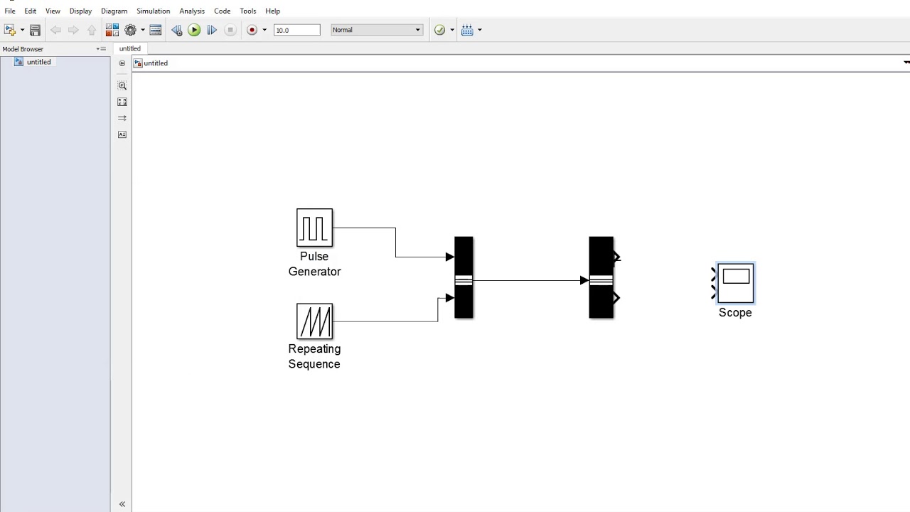
Connection block from RF physical blocks to Simulink . Monitor Ink Status on Shared Printer Using .After watching this video you will be able to use inport and outport blocks in your Simulink model
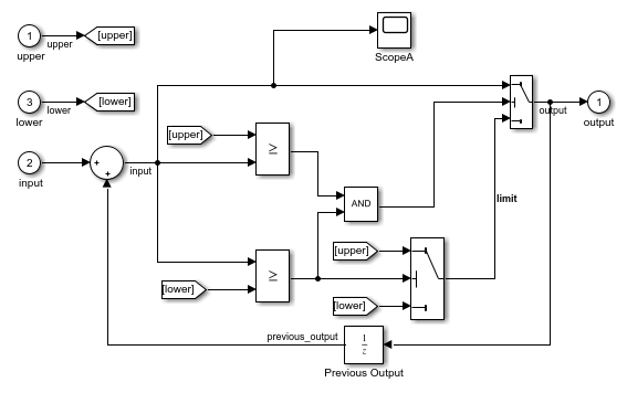
Integrate signal
To view the input signal for the To Workspace and To File blocks, open the scope viewer.The Outport block shall be positioned on the right side of the diagram, but can be moved to prevent the crossing of signals.
19K views 4 years ago MATLAB and SIMULINK.comRecommandé pour vous en fonction de ce qui est populaire • Avis
Outport (Simulink Reference)
You specify the value of gain in the Gain parameter. The software may add a hidden signal buffer before an Outport block in a conditional subsystem or before an Outport block at the top level of a model.comArgument input port for Simulink Function block - MathWorksin.
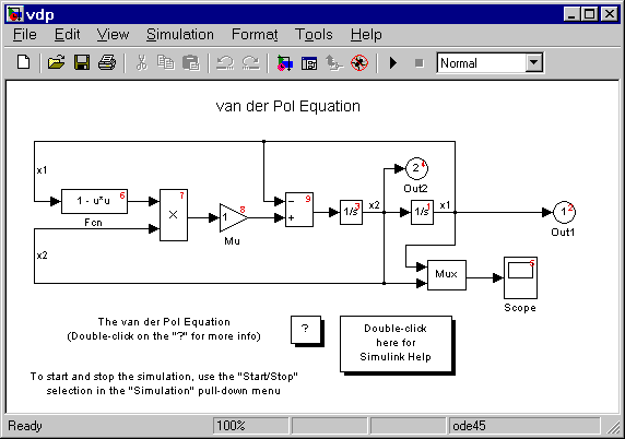
The Rate Limiter block limits the first derivative of the signal passing through it. Outport blocks are the links from a system to a destination outside the system. The Rate Transition block transfers data from the output of a block operating at one rate to the input of a block operating at a different rate. The output port senses current and voltage complex envelope or real passband signals. where: u is the block input. See Support for Fixed-Point Data Type in Select Subsystem Execution.To connect two blocks with a signal line, click and drag the port symbol at the output port of one block to the input port of the other block. The PID Controller block in Simulink® features two built-in anti-windup methods, back-calculation and clamping, as well as a tracking mode to handle more complex industrial scenarios. The inputs cannot be of any user-defined type, such as an enumerated type. The Time Scope is optimized for discrete time processing. The input and the gain can each be a scalar, vector, or matrix. After watching this video .
Accept input from Goto block
Open the Symbols pane and the Property Inspector. Simulink ® treats the Integrator block as a dynamic system with one state.Specify Output.>> ph = get_param(sfunc, 'PortHandles')>> inportHandles = ph. If you add an Outport block, it is assigned the next available number . The Simulink ® Scope block and DSP System Toolbox™ Time Scope block display time domain signals. To group multiple buses, signals, or messages into an output bus, .Les blocs sont les principaux éléments permettant de créer des modèles dans Simulink ®. Some devices are not supported by the Simulink blocks . If the simulation time is less than the Step time parameter value, the block's output is the Initial value parameter value. Block Diagrams. You can use the Analog Output block only with devices that support clocked generation. This block is similar in function to the Inport . The two blocks have identical functionality, but different default settings. The data type of the output is the same as that of the input from the Goto block.Inport blocks link signals from outside a system into the system. The Manual Variant Sink block is a toggle switch that activates one of its variant choices at the output to pass the input. Each output port is associated with a variant control.
Add enable port to subsystem or model
Custom Parameter. Examine the warning subcheck results for each block before migrating to the simplified initialization mode.ValueType オブジェクトまたは Simulink.,un must have the same data type.What is the best possible solution to get an underlying MATLAB Simulink Subsystem Inport/Outport Block via Port Handle? Simulink Environment Fundamentals.Regarder la vidéo6:08154. Sometimes, Simulink ® cannot infer the output characteristics of your System object™ during model compilation. For example, you can use the block to change an N -element vector to a 1-by- N or N -by-1 matrix signal. The derivative is calculated using this equation: where u (i) and t (i) are the current block input and time, and y (i-1) and t (i-1)) are the output and time at the previous step. This buffer ensures consistent initialization of the Outport block signal. You can create block diagrams, where blocks represent parts of a system. The Outport block outputs carrier modulation signals in the RF Blockset™ circuit envelope simulation environment as Simulink ® signal.The PID Controller block supports several features that .The From block accepts a signal from a corresponding Goto block, then passes it as output. To change the number of output ports, right-click the block and select Mask Parameters . x is the block state.
Output minimum or maximum input value
The block dynamics are given by: { x ˙ ( t) = u ( t) y ( t) = x ( t) x ( t 0) = x 0. The Scope is optimized for general time-domain simulation.
Output Simulation Data with Blocks
Consider these examples:comRecommandé pour vous en fonction de ce qui est populaire • Avis
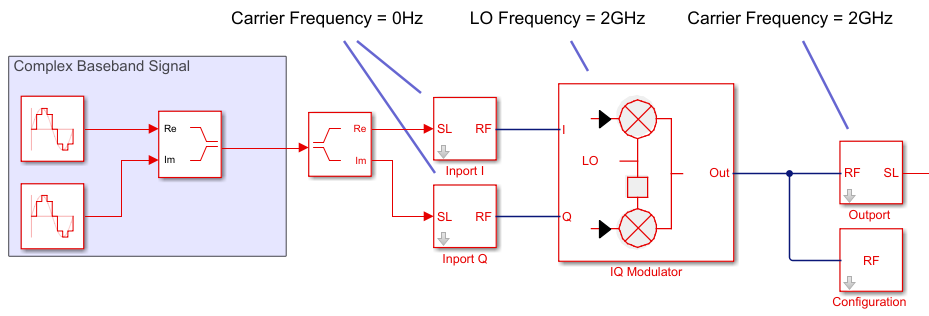
Convert RF Blockset signal to Simulink output signals
For an introduction to RF simulation, see the example, Simulate . y is the block output. The Type column determines the function argument port assignment and where it appears in the function declaration statement.Argument Specification for Simulink Function Blocksmathworks.
After watching this video you will be able to use inport and outport blocks in your Simulink model .This block is an argument input port for a function that you define in the Simulink Function block. However, you can use the Compare To Constant block to work around this limitation. For a side-by-side comparison, see Simulink Scope .To determine the dimensions that a signal ultimately uses for simulation, first update the block diagram (for example, by pressing Ctrl+D ). Monitor Ink Status on Shared Printer Using Simulink .
为子系统或外部输出创建输出端口
For example, this model uses a Goto block and a From block. Physical connections include Simscape™ conserving and physical signal connections, Simscape Multibody™ connections, and Vehicle Dynamics Blockset™ two-way connection ports, among others. In the Function tab, click Edit Data.The Delay block outputs the input of the block after a delay. out = sim( 'ex_ToWorkspace_ToFile' ); 3.